Last updated: August 2026 | Reading time: 12 minutes

Outdoor lighting is no longer an afterthought in architecture and landscaping—it is a design layer that defines safety, atmosphere, and brand identity after sunset. Whether you are sourcing for a luxury hotel garden, a commercial plaza, or a high-end residential estate, the landscape lighting manufacturer you choose will directly determine installation cost, maintenance cycles, and end-user satisfaction.

In 2026, the market is flooded with suppliers claiming “factory-direct” pricing and “premium” quality. Yet many B2B buyers still struggle with the same questions: How do you separate a true manufacturing partner from a trading middleman? Which certifications actually matter for your target market? And when does a China-based architectural lighting supplier make more sense than a US or EU brand?

This guide replaces generic “Top 10” lists with a practical evaluation framework. By the end, you will have a 7-dimension scoring model, a procurement checklist, and a clear sense of whether your next project needs a catalog brand or a custom LED lighting OEM partner.

📥 Quick Start: Want the product specs first? Browse KWT’s 2026 Architectural Lighting Catalog or request a sample kit for your next project.

Why Manufacturer Selection Matters More in 2026

The global outdoor LED lighting market continues to shift from commoditized bulk orders to specification-driven projects. Architects and lighting designers now expect manufacturers to deliver photometric accuracy, smart-control compatibility, and material longevity—not just lumen output.

Choosing the wrong outdoor LED lighting manufacturer creates hidden costs that appear months after installation:

  • Recertification delays when sub-suppliers swap LED chips or drivers without notice.
  • Color-shift failures caused by poor thermal management in custom housings.
  • Smart-system incompatibility because the fixture was never tested against DALI-2 or 0-10V dimming protocols.
  • Warranty disputes when the “5-year guarantee” is underwritten by a shell company with no local service presence.

Avoiding these problems requires moving beyond brand name recognition and evaluating manufacturers against technical, operational, and commercial criteria.

5 Landscape Lighting Trends Shaping Manufacturer Capabilities in 2026

Before you score a manufacturer, understand what the market now demands. These five trends separate future-ready suppliers from legacy catalog vendors.

1. Smart Control & IoT Integration

Static on/off circuits are disappearing from premium projects. Buyers now expect zoning, dimming, and RGBW scene control via DALI-2, Matter, or proprietary apps. A capable manufacturer should offer firmware-upgradable drivers and pre-tested control compatibility—not aftermarket retrofit kits.

2. Solar-Hybrid & Ultra-Low Voltage Systems

For remote landscape zones without trenching access, solar-hybrid path lights and 12V hub-based systems reduce infrastructure cost. Manufacturers need to prove battery-management IC quality and solar-panel degradation curves, not just daytime brightness specs.

3. RGBW Dynamic Scene Lighting for Hospitality

Hotels and resorts want “Instagrammable” nightscapes. This requires fixtures with independent RGBW channels, high CRI white diodes (>90), and optical systems that prevent color fringing on foliage and water features.

4. Ultra-Slim Magnetic Track Systems Moving Outdoors

Originally an indoor architectural tool, magnetic track systems are now being specified for covered outdoor pavilions, restaurant terraces, and retail facades. Manufacturers with in-house extrusion, anodizing, and magnetic-module design capability can deliver IP-rated track profiles that standard catalog brands cannot.

5. Sustainability Compliance & Circular Design

EU CBAM regulations and US LEED v5 standards are pushing manufacturers to disclose embodied carbon, use recyclable aluminum alloys, and design for component-level replacement rather than full-fixture disposal.

The 7-Dimension Manufacturer Evaluation Framework

Use this model to score any landscape lighting manufacturer objectively. We have applied it across US, EU, and China suppliers for over a decade.

① Technical R&D Capability

Ask for evidence of in-house optical design (LightTools or Dialux simulations), thermal modeling, and custom PCB layout. Trading companies rarely have these competencies; they simply relabel generic modules. A true manufacturing partner should produce IES files, LM-79 reports, and TM-21 lumen-maintenance projections on demand.

② Certification & Compliance

Do not accept certificate screenshots at face value. Verify CE, UL, ETL, ENEC, and RoHS documents through the issuing body’s online portal. For North American projects, UL1598 or ETL-listed outdoor fixtures are non-negotiable. For EU public tenders, ENEC plus CE marking is the baseline. ISO9001 and ISO14001 indicate process maturity, not product safety.

③ Production Capacity & Lead Time

In-house die-casting, CNC, powder-coating, and SMT lines give manufacturers control over quality and scheduling. Ask for a facility video or virtual tour. A 4-week sample turnaround and 6–8 week bulk lead time are realistic for custom projects. Anything faster often means subcontracting without disclosure.

④ Material & Craftsmanship

Coastal and high-salinity environments demand 316 stainless steel or solid sand-cast bronze. Inland commercial projects can use powder-coated aluminum if the pre-treatment and salt-spray testing (ASTM B117) are documented. For lenses, tempered glass outperforms polycarbonate in UV resistance over 5+ years.

⑤ OEM/ODM Flexibility

If you are building your own lighting brand, you need a partner who can move from concept sketch to functional prototype in under 30 days. Evaluate their mold-development capability, color-temperature binning control, and private-label packaging workflows. Full in-house vertical integration—from electronics to finishing—is the only way to guarantee that your custom design does not get quietly outsourced to a third workshop.

⑥ Component Transparency

Demand declared bill-of-materials for LED chips (CREE, OSRAM, LUMILEDS), drivers (Mean Well, Inventronics, Osram OT), and optics (LEDIL, Khatod). Reputable manufacturers will specify alternate sources only with prior written approval.

⑦ After-Sales & Warranty Structure

A 20-year warranty on a bronze fixture is credible only if the manufacturer has been in business longer than the warranty period and maintains replaceable LED modules. For electronics, a 5-year driver warranty is the industry benchmark. Check whether warranty claims are handled via local distributors or direct factory RMA.

💡 Tip: KWT maintains full in-house production—from SMT and CNC turning to powder coating and final assembly—allowing complete BOM transparency and rapid design iteration. Talk to our engineering team about your custom project.

China Manufacturers vs. US/EU Brands: An Honest Comparison

B2B buyers often frame this as “cheap China vs. premium West.” The reality is more nuanced. Each origin has structural strengths and weaknesses.

CriteriaUS/EU Specialist BrandsEstablished China Manufacturers
Unit PriceHigher; covers local warehousing & serviceLower at equivalent spec; MOQ scaling
CustomizationLimited to catalog variantsDeep ODM: housing, optics, firmware, packaging
Lead Time (Bulk)2–4 weeks (local stock)6–10 weeks (sea freight) / 3–5 days (air)
Certification SupportPre-certified for home marketCan acquire UL/ETL/ENEC per project; more flexible
Smart Control R&DMature app ecosystems (Kichler, FX)Rapid hardware iteration; DALI/Matter integration
Best ForResidential retrofits, local contractor loyaltySpec-driven hospitality, retail, mixed-use developments

For architects and developers managing multi-site rollouts, a China-based architectural lighting supplier with EU/US certification support and a Barcelona or Frankfurt design liaison can deliver 70% of the customization value at 50–60% of the landed cost—provided you verify the 7 dimensions above before placing bulk orders.

5 Common Pitfalls When Sourcing Landscape Lighting

1. IP Rating Inflation

A supplier claims “IP68.” Ask for the test report number and testing lab (SGS, TÜV, Intertek). IP68 requires submersion depth and duration data; without it, the claim is meaningless.

2. Driver Brand Bait-and-Switch

The sample arrives with a Mean Well driver. The bulk shipment uses an unbranded domestic equivalent. Specify driver brand and model in the PO, and reserve the right to third-party inspection.

3. Sample-to-Bulk Quality Drift

Hand-polished prototypes often look better than mass-production units. Lock surface-finish standards (Ra values), coating thickness (μm), and color-temperature tolerance (±100K) in your quality agreement.

4. Ignoring Photometric Data

Without IES files and Dialux proof-of-concept, your landscape lighting design becomes guesswork. Reputable manufacturers provide these before mold investment.

5. Underestimating Smart Control Compatibility

A fixture may dim beautifully on a bench power supply but fail to integrate with your building’s BACnet or KNX backbone. Demand protocol-compatibility documentation during the sampling phase.

Manufacturer Spotlight: Global Players Worth Evaluating

Below is a concise, non-ranked reference list based on the 7-dimension framework. Use it as a starting point for your own due diligence.

US & EU Specialists

  • VOLT Lighting — Strong IP68-rated fixtures and aggressive price points. Best for residential contractors needing quick, proven SKUs.
  • Kichler — Extensive catalog, smart-app integration, and warming-lens optics. Ideal for design-build firms serving the North American mid-market.
  • FX Luminaire — Luxor zoning controllers and coastal-grade finishes. Distribution-only model; not suitable for direct OEM relationships.
  • CAST Lighting — Solid sand-cast bronze construction with lifetime-grade material integrity. Premium residential and heritage projects.

China Full-Range & Custom Manufacturers

  • RC Lighting — Broad architectural and landscape catalog with OEM/ODM flexibility. Strong component sourcing (CREE, OSRAM, Mean Well).
  • CHZ Lighting — High-volume street and garden lighting with solid international certification coverage (CE, RoHS, ENEC).
  • KWT (King Watt Opto-Electronic) — Since 2006, KWT has operated as a full-stack architectural lighting supplier from Shenzhen, with a Barcelona Creative Lab (BCL) for co-design with European architects and lighting designers. Unlike catalog-only brands, KWT controls the entire value chain: PCB assembly, CNC machining, die-casting, powder coating, and final testing. This vertical integration makes KWT particularly strong for spec-driven projects—hotels, retail flagships, and mixed-use developments—where fixture dimensions, CCT, beam angle, and control protocol must deviate from standard SKUs. Browse the 2026 catalog or submit a custom brief.

Your Procurement Checklist

Before you sign a purchase order, confirm the following:

  1. ☐ I have verified the manufacturer’s certifications through the issuing body’s online database.
  2. ☐ I have received IES files and/or Dialux simulations for the proposed fixtures.
  3. ☐ LED chip brand, driver brand, and lens material are specified in the quotation.
  4. ☐ IP/IK test reports reference an accredited third-party lab.
  5. ☐ The sample was produced on the same SMT and assembly lines as bulk production.
  6. ☐ Warranty terms, RMA process, and spare-part availability are documented.
  7. ☐ Smart-control compatibility (DALI, 0-10V, wireless) is tested and confirmed.
  8. ☐ Surface-finish and color-tolerance standards are written into the quality agreement.
  9. ☐ The manufacturer holds ISO9001 and can provide a production-facility audit (virtual or physical).
  10. ☐ I understand the total landed cost, including tooling amortization, shipping, duties, and customs clearance.

Frequently Asked Questions

What is the typical MOQ for custom landscape lighting from a China manufacturer?

For standard housing modifications (color, CCT, logo), MOQs usually start at 100–200 units. For full ODM with new mold investment, expect 500–1,000 units depending on fixture complexity. Some manufacturers offer mixed-SKU MOQs for project-based buyers.

How do I verify if a manufacturer’s CE or UL certificate is real?

For UL/ETL, use the UL Product iQ database. For CE, check the Notified Body’s EU NANDO registry. Always cross-reference the certificate number, product model, and manufacturer legal name.

What IP rating do I need for coastal landscape lighting?

Coastal and marine environments require IP67 as a minimum for fixtures and IP68 for submerged units (fountain lights). Equally important is the housing material: 316 stainless steel or solid bronze resists salt corrosion far better than powder-coated aluminum.

Can one manufacturer handle both landscape and architectural lighting?

Yes, but verify their core competence. Many landscape specialists lack the optical precision for indoor architectural downlights or magnetic track systems. Conversely, architectural manufacturers with outdoor IP-rated lines can deliver aesthetic consistency across interior and exterior zones—critical for hospitality and retail brands.

How long does it take from design approval to mass production?

Prototype: 2–4 weeks. Mold fabrication (if needed): 3–5 weeks. First-article inspection: 1 week. Bulk production: 4–6 weeks. Add 3–5 weeks for sea freight to Europe or North America. Air freight reduces transit to 5–7 days but increases unit cost significantly.

What is the difference between OEM and ODM in lighting manufacturing?

OEM means the manufacturer builds your design under your brand. ODM means the manufacturer offers an existing design platform that you customize (housing finish, CCT, beam angle, packaging). ODM is faster and lower risk; OEM gives you full IP ownership but requires higher upfront investment.

Are smart landscape lighting systems compatible with existing home automation?

Compatibility depends on the protocol. DALI-2 and 0-10V are widely supported by professional automation systems. Consumer-grade Matter and Wi-Fi apps require specific hub integration. Always request a protocol-integration sheet before specifying a fixture for smart projects.

Why do some LED landscape lights fail within two years?

Premature failure is almost always caused by one of three factors: thermal design flaws (LED junction temperature too high), driver electrolyte drying in high-heat enclosures, or moisture ingress through compromised gaskets. A manufacturer with in-house thermal simulation and IP-testing capability can prevent these issues at the design stage.

Conclusion: Move Beyond Lists, Build a Scoring System

The internet is already saturated with “Top 10 landscape lighting manufacturers” articles that read like business-card collections. What B2B buyers actually need is a decision framework: a way to score suppliers on R&D depth, material integrity, certification honesty, and post-sale accountability.

Use the 7-dimension model and the procurement checklist above to vet your shortlist. If your project demands more than catalog SKUs—if you need custom optics, magnetic track integration, or a lighting family that carries one design language from lobby to garden—prioritize manufacturers with in-house vertical integration and a proven record of architect collaboration.

That is precisely where a landscape and architectural lighting manufacturer with design-lab capability and full production control becomes indispensable.

Ready to Evaluate Your Next Lighting Partner?

KWT has been developing custom LED architectural and landscape luminaires since 2006. From our Barcelona Creative Lab to our Shenzhen production floor, we control every step of the value chain.

📖 Browse 2026 Catalog ✉️ Request a Custom Quote

ISO9001 certified • CE / UL / ETL project support • OEM & ODM welcome
IEC 60529 Reference

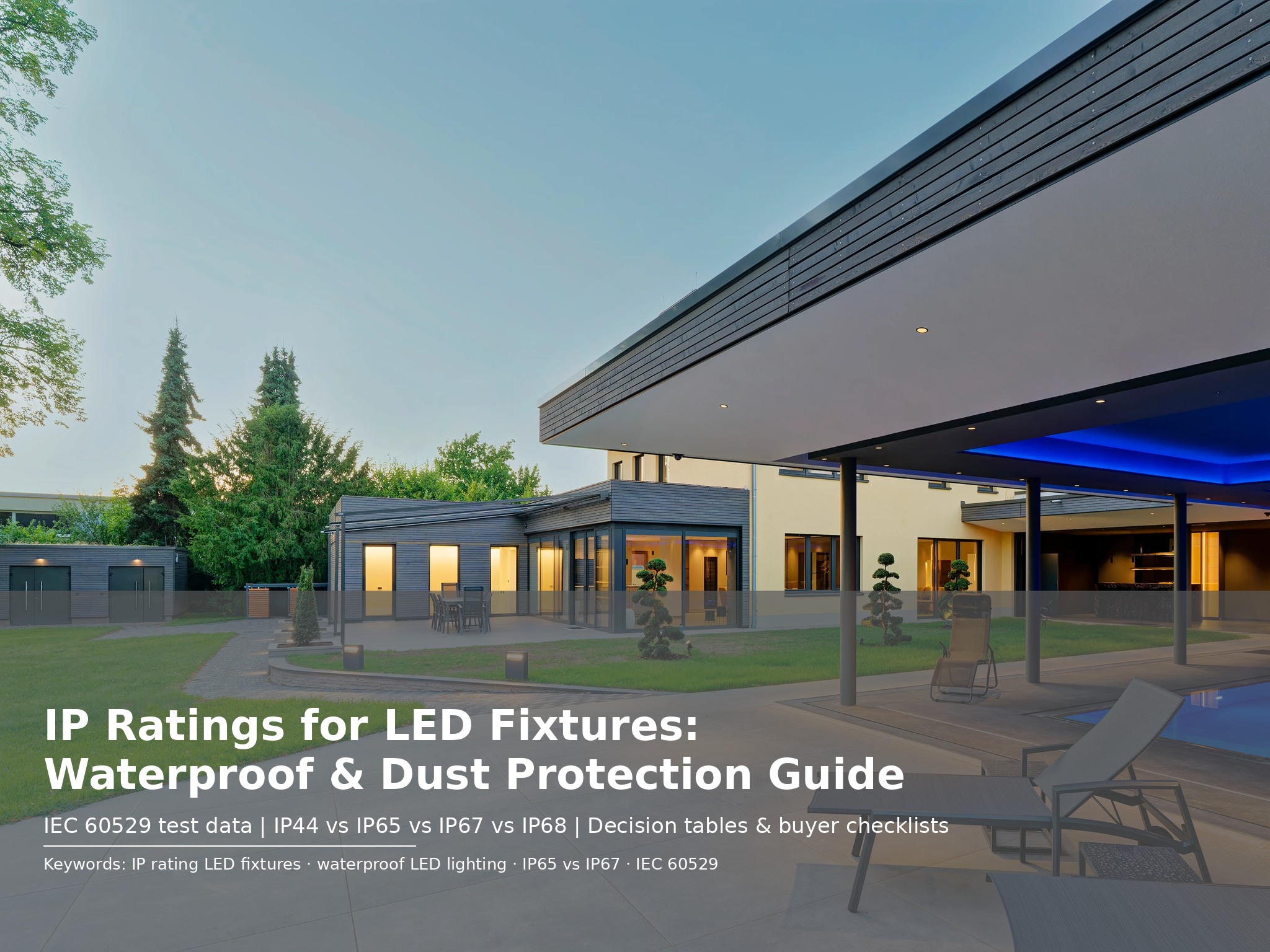
IP Rating for LED Fixtures: Standards, Chart & Selection Guide

An IP rating classifies how well an LED fixture enclosure blocks solids and liquids. The two digits after “IP” follow IEC 60529 — a standardized testing protocol that replaces vague marketing terms like “waterproof” with precise, verifiable numbers. Use this guide to match the correct IP code to your project environment.

Standard: IEC 60529:2013    Last updated: 2026-08-14    Audience: Specifiers, contractors, procurement

Quick Reference — IP Code Decoder

IP ratings use two digits. The first digit (0–6) measures solid protection. The second digit (0–9) measures liquid protection. Both are required for a complete rating.

CodeFirst Digit (Solids)Second Digit (Liquids)
IP20Protected against fingers (≥12.5mm)No liquid protection
IP44Protected against wires (≥1mm)Protected against splashing water
IP54Dust protected (limited ingress)Protected against splashing water
IP65Dust tight (no ingress)Protected against water jets
IP67Dust tight (no ingress)Protected against temporary immersion
IP68Dust tight (no ingress)Protected against continuous submersion

What Is an IP Rating?

An IP (Ingress Protection) rating is a two-digit code defined by IEC 60529:2013 that classifies the degree of protection an electrical enclosure provides against solid objects and liquids. The code replaces subjective marketing language — “waterproof,” “dustproof,” “weather-resistant” — with testable, standardized criteria.

For LED fixtures, the IP rating determines whether a light survives its environment. An incorrectly specified rating causes driver corrosion, LED lumen depreciation, thermal failure, and voided warranties. A correctly specified rating ensures the fixture reaches its design life — typically 50,000 hours (L70/B50).

IP Code ElementRangeMeasuresExample
First digit0–6Solid particle protection6 = dust-tight
Second digit0–9Liquid ingress protection8 = continuous submersion
Letter suffixA–H, M, S, WSupplementary information (rare in LED)IP66K = high-pressure steam
Source: IEC 60529:2013, Degrees of protection provided by enclosures (IP Code). International Electrotechnical Commission, Geneva. Test conditions are mandatory — a manufacturer cannot claim IP65 without documented evidence of testing.

IP Rating Standards & Exact Test Conditions

IEC 60529 specifies exact test apparatus, durations, and pass/fail criteria. A manufacturer’s claim is only valid if an accredited laboratory (TÜV, SGS, Intertek, or equivalent) performed the test. Here are the exact conditions for each digit relevant to LED lighting.

First Digit: Solid Protection (0–6)

RatingProtected AgainstTest ObjectTest Duration
0No protection
1Objects ≥ 50 mm50 mm sphere
2Fingers ≥ 12.5 mm12.5 mm sphere, 80 mm long
3Tools ≥ 2.5 mm2.5 mm rod
4Wires ≥ 1.0 mm1.0 mm wire
5Dust (limited ingress)Talc powder chamber, partial vacuum2 hours
6Dust tight (no ingress)Talc powder chamber, full vacuum2 hours

Second Digit: Liquid Protection (0–9)

RatingProtected AgainstTest ApparatusTest ConditionDuration
0No protection
1Vertical drippingDrip box1 mm/min rainfall10 min
2Dripping at 15° tiltDrip box, 4 positions3 mm/min rainfall2.5 min per position
3Spraying waterOscillating tube or spray nozzle0.7 L/min at 50–150 kPa1 min/m², min 5 min
4Splashing waterOscillating tube or spray nozzle10 L/min at 50–150 kPa1 min/m², min 5 min
5Water jets6.3 mm nozzle12.5 L/min at 30 kPa, 3 m distance1 min/m², min 3 min
6Powerful water jets12.5 mm nozzle100 L/min at 100 kPa, 3 m distance1 min/m², min 3 min
7Temporary immersionImmersion tank1 m below surface30 min
8Continuous submersionImmersion tankDepth and time per manufacturer specPer manufacturer
Note: IPX8 means the liquid protection digit (8) was tested, but the solid protection digit (X) was not. For outdoor LED fixtures, always demand a full two-digit rating. A fixture rated IPX8 may allow dust ingress that destroys the driver even if it survives submersion.
[INSERT CHART: bar chart showing water pressure (kPa) across IP ratings — IP3: 50–150, IP4: 50–150, IP5: 30, IP6: 100, IP7: 10 (static head), IP8: variable]

IP Rating Chart for LED Fixtures

Use this chart to match common IP ratings to LED fixture types and project environments. All ratings assume IEC 60529:2013 compliance with third-party test reports.

IP RatingSolidLiquidLED Fixture TypeEnvironmentKWTLED Series
IP20FingersNoneCOB downlight, panel lightDry office, retail ceilingDL-COB Series
IP44WiresSplashingMirror light, vanity barBathroom (general zones)BV-Mirror Series
IP54Dust protectedSplashingSurface ceiling light, bulkheadCovered patio, corridorSL-Surface Series
IP65Dust tightWater jetsWall light, flood light, high-bayExposed facade, parkingWL-Outdoor Series
IP67Dust tightTemporary immersionInground uplight, deck lightPool edge, fountain, deckIG-Inground Series
IP68Dust tightContinuous submersionUnderwater pool light, pond lightSwimming pool, pond, fountainUW-316L Series
From our test lab: We test every IP68 batch at 2 meters for 72 hours — beyond the IEC minimum — because pool installations often exceed 1 meter depth. All IP65+ fixtures undergo 100% gasket compression verification before shipment.

IP65 vs IP68: Key Differences for LED Projects

IP65 and IP68 are the two most commonly confused ratings in LED specification. Both are dust-tight. The difference is liquid protection — and that difference determines whether your fixture survives or fails.

FactorIP65IP68Winner / Use Case
Dust protectionDust tight (6)Dust tight (6)Equal
Water testWater jets, 6.3 mm nozzle, 12.5 L/minContinuous submersion, depth per spec
Max water pressure~30 kPa (jet at 3 m)Variable, typically 10–300 kPa staticIP68 for pressure
Submersion safe?NoYesIP68
Typical depth ratingNot rated1–3 meters, 24–168 hoursIP68
Unit cost premiumBaseline+40–60%IP65 for budget
Best forBuilding facades, outdoor walls, parkingUnderwater pools, ponds, fountainsDepends on environment
KWTLED exampleWL-Outdoor SeriesUW-316L Series

IP65 resists rain and pressure washing. It does not resist immersion. The water pressure at 0.3 meters depth exceeds the IP65 test pressure within minutes. For any fixture installed below water level — even temporarily during flooding — specify IP68.

Critical: Installing an IP65 fixture underwater voids the warranty and creates an electrical safety hazard. We have replaced 24 IP65 wall lights in a Phuket resort pool after 72 hours of submersion failure. The replacement cost exceeded $18,000.
[INSERT CHART: radar chart comparing IP65 vs IP68 across dust protection, water jet resistance, immersion depth, thermal performance, and unit cost]

IP Rating by Application

Match your project environment to the minimum required IP rating. Over-specification wastes budget. Under-specification guarantees failure.

ApplicationMin RatingRecommendedWhy
Dry office ceilingIP20IP20No moisture risk; maximum heat dissipation
Hotel bathroom (general)IP20IP44Splash and steam protection
Hotel bathroom (shower zone)IP44IP65Direct spray and cleaning chemicals
Covered walkwayIP20IP54Occasional spray and dust
Exposed building facadeIP54IP65Rain, jet washing, dust
Parking structureIP54IP65Vehicle spray, pressure cleaning
Pool deck / fountain edgeIP54IP67Temporary immersion from splashing
Underwater (pool, pond)IP67IP68Continuous submersion; depth-rated
Coastal outdoorIP65IP68 + 316L SSSalt spray corrodes standard housings
Industrial / warehouseIP54IP65Dust and high-pressure cleaning
Note: For coastal projects in Florida, Dubai, or Southeast Asia, specify 316L stainless steel housing in addition to IP68. Standard 304 stainless steel corrodes in salt-chlorine water within 18 months. We provide ASTM B117 salt-spray test reports (1000 hours) for all 316L underwater fixtures.

3 Specification Mistakes That Cost Projects Thousands

Mistake 1 — Treating IP65 as Submersible

IP65 resists water jets. It does not survive immersion. Submerging an IP65 fixture destroys the driver within hours. For underwater LED lighting, only IP68 with confirmed depth ratings qualifies. Always verify the test certificate covers submersion, not just jet exposure.

Mistake 2 — Ignoring the First Digit

A warehouse in Riyadh specified IPX5 fixtures for outdoor loading bays. Within 8 months, dust blocked heat sinks and caused 40% lumen depreciation. The “X” meant solid protection was never tested. In desert, industrial, or agricultural environments, always specify IP6X — dust-tight — regardless of liquid exposure.

Mistake 3 — Uniform Rating Across All Zones

A Lisbon hotel specified IP65 downlights for every bathroom zone. The dry vanity area needed only IP20. The steam shower needed IP65. Result: 30% overspend on vanity fixtures, plus one shower failure from steam seal degradation after 18 months. Map each zone individually per IEC 60364-7-701.

Pre-installation checklist: (1) Document dust and water exposure per fixture. (2) Request IEC 60529 test report with exact model number match. (3) Confirm housing material for chemical exposure. (4) Inspect gasket compression on sample. (5) Verify thermal compensation for sealed housings.

Housing Materials for Wet & Corrosive Environments

The IP rating protects against ingress. The housing material protects against corrosion. A perfectly sealed IP68 fixture with the wrong housing material still fails.

MaterialCorrosion ResistanceBest ForAvoid In
ADC12 die-cast aluminum + powder coatGood (indoor, dry outdoor)IP20–IP65, general outdoorChlorinated water, salt spray
304 stainless steelGood (fresh water, mild chemicals)IP65–IP67, pools with standard water treatmentSaltwater, high-chlorine environments
316L stainless steelExcellent (salt, chlorine, acids)IP68, coastal, marine, high-chlorine poolsBudget-constrained dry applications
PC (polycarbonate)Good (UV stable grades)IP65, impact-resistant outdoorHigh-temperature environments (>85°C)
ABS plasticFair (indoor only)IP20–IP44, budget indoorOutdoor UV, high heat, chemicals
From our test lab: During batch testing for a Maldives resort, 304 stainless steel housings showed pitting corrosion after 14 months of salt-chlorine exposure. 316L showed zero degradation after 36 months. We now specify 316L as standard for all IP68 pool lights.

What Contractors Get Wrong About IP Ratings

“IP65 Is the Highest Rating for Outdoor Use”

IP65 is designed for water jets — rain and pressure washing. It is not designed for submersion, prolonged condensation, or high-pressure cleaning equipment. A facade cleaning crew using a 150-bar pressure washer will destroy IP65 seals. For standing water or submersion, IP67 or IP68 is required.

“Higher IP Rating Always Means Better”

IP68 fixtures cost 40–60% more than IP65 and run hotter due to sealed enclosures. In a dry office ceiling, IP68 has no advantage over IP20 — but a shorter lifespan from thermal stress. The correct IP rating is the minimum rating that covers the environmental risk, not the maximum available.

“IP Ratings Are Just Marketing Labels”

IP ratings are standardized, testable, and legally enforceable. A manufacturer cannot claim IP68 without accredited laboratory testing. At KWTLED, every IP68 batch is tested at 2 meters for 72 hours. The difference between a marketing claim and a test report is the difference between a valid warranty and a voided one.

FAQs About IP Ratings for LED Fixtures

What does IP stand for in LED lighting?

IP stands for Ingress Protection. It classifies how well an LED fixture enclosure blocks solids and liquids per IEC 60529. The first digit (0–6) measures solid protection. The second digit (0–9) measures liquid protection.

What is the difference between IP65 and IP68?

IP65 is dust-tight and resists water jets (6.3 mm nozzle, 12.5 L/min, 3 min). IP68 is dust-tight and rated for continuous submersion at a depth and duration specified by the manufacturer. IP65 is for outdoor walls. IP68 is for underwater use.

What IP rating do I need for outdoor LED lights?

For exposed outdoor locations subject to direct rain, IP65 is the industry standard. For covered patios and verandas, IP54 is sufficient. For underwater applications — pools, fountains, ponds — use IP68 with confirmed depth ratings.

Can IP65 lights be used in a bathroom?

Yes, for general bathroom zones outside the shower enclosure. For shower enclosures (Zone 2 under IEC 60364-7-701), IP44 is the legal minimum and IP65 provides better protection against direct spray and steam. Do not use IP65 fixtures inside the bath itself — that requires IPX7.

Is IP68 better than IP67?

Yes, for submersion. IP67 is rated for temporary immersion — 30 minutes at 1 meter depth. IP68 is rated for continuous submersion at a depth and duration specified by the manufacturer. For pool lighting, IP68 is the only reliable choice.

Does IP rating affect LED lifespan?

Yes. A correctly specified IP rating prevents moisture and dust from reaching the driver and LEDs. An IP20 fixture in a wet environment typically fails within 6–18 months. The same LED chip in an IP65 housing lasts 50,000+ hours.

What does IPX8 mean on an LED fixture?

IPX8 means the manufacturer tested for continuous submersion but did not test solid protection. The “X” means “not tested,” not “rated.” For outdoor use, insist on a full two-digit rating like IP68. A fixture rated IPX8 may allow dust ingress that destroys the driver.

Can I get custom IP ratings for private-label LED products?

Yes. At KWTLED, our OEM program supports custom sealing designs, gasket materials (silicone, fluorosilicone, EPDM), and IP certification for private-label fixtures starting at 50 units MOQ. Every custom design is validated with submersion testing before bulk production.

How do I verify a manufacturer’s IP claim?

Request the IEC 60529 test report from an accredited laboratory (TÜV, SGS, Intertek). Verify the report date is within 2 years, the test sample matches your exact model number, and test conditions match your installation environment. At KWTLED, we provide test reports with every IP-rated bulk order.

What is the lead time for IP-rated LED orders?

Standard stock IP65 and IP68 modules: 3–4 weeks. Custom IP68 with 316L stainless steel or custom CCT: 5–7 weeks. Large projects (500+ modules) can use phased delivery aligned to construction milestones.

Specify IP-rated LED fixtures for your next project

Get IEC 60529 test reports, sample validation, and OEM custom sealing designs. MOQ from 50 units.

© 2026 KWTLED Lighting — Lighting Standards Reference
kwtled.com


Lighting Knowledge

Installation Guide

How to Install LED Downlights in Commercial Spaces: Complete Contractor’s Guide

Installing LED downlights the wrong way in commercial environments leads to overheating, flickering, failed inspections, and costly rework. This guide gives contractors a complete framework — from ceiling assessment and layout calculation to wiring, fire safety, compliance, and project handover. Whether you work on office fit-outs, retail rollouts, or hospitality renovations, you need a method that passes inspection the first time.

Last updated: 2026-08-14 Audience: Electrical contractors, project engineers, lighting technicians, procurement & B2B buyers

What Is Commercial LED Downlight Installation (And How Does It Differ From Residential)?

Before you cut the first hole, you need to understand what separates commercial LED downlight installation from residential work. A commercial installation is not simply “more fixtures.” It is a coordinated electrical, structural, and compliance operation where scale, ceiling variety, and regulatory scrutiny multiply the consequences of every decision.

The best way to install LED downlights in a commercial space is to combine pre-installation planning, ceiling-type-specific methods, and post-installation testing. Get any of these wrong, and you face rework, code violations, or premature fixture failure. Commercial installations differ from residential jobs in three ways: scale (50+ fixtures per floor), compliance (fire-rated ceilings and MEP coordination), and ceiling variety (gypsum, T-grid, or concrete).

The Anatomy of a Commercial Downlight System

A complete commercial downlight installation consists of four integrated layers. Understanding each one prevents errors that only surface during inspection.

Ceiling Substrate: The backbone of every installation decision. Gypsum board, suspended T-grid, and exposed concrete each demand different cutting methods, mounting hardware, and fire-safety protocols. The substrate determines whether you recess, surface-mount, or suspend — and whether you need fire-rated enclosures. Explore our fire-rated downlight series and compatibility chart →

LED Fixture & Driver: The downlight module contains the LED COB or SMD array, precision optics, and thermal management housing. The driver sits remotely in the plenum or an electrical closet, converting mains AC to DC. Driver placement dictates cable run lengths, voltage drop calculations, and heat dissipation strategy. In commercial projects, specify drivers with 0-10V, DALI-2, or Bluetooth Mesh dimming compatibility.

Electrical Infrastructure: Circuit capacity, grounding, and control wiring must comply with local codes (NEC in the US, BS 7671 in the UK). Commercial circuits typically run at 80% breaker capacity maximum. Long cable runs require voltage drop verification. Every metal-housed fixture needs earth bonding.

Fire & Safety Systems: Fire-rated ceilings require intumescent sealant or fire hoods at every penetration. Sprinkler clearances (300 mm per NFPA 13), smoke detector positioning, and thermal insulation clearances (50 mm for non-IC fixtures) are not optional details — they are inspection checkpoints.

From Our Engineering Team: In Q2 2024, we audited a retail rollout in Warsaw where the contractor installed 64 non-IC-rated downlights directly against thermal insulation. Within eight months, 23 drivers failed due to overheating. The replacement cost — modules plus emergency shipping plus ceiling reopening — exceeded $6,800. Always verify IC rating against ceiling insulation type before the first cut.

Why Ceiling Type Matters More Than Fixture Choice

Gypsum board ceilings dominate modern offices and retail. They allow clean recessed installation but require fire-rated enclosures in rated assemblies. Cutting tolerance is ±2 mm — beyond that, trim rings will not cover gaps.

T-grid suspended ceilings offer easy access but limited load capacity. A 12W downlight with driver weighs 0.8–1.2 kg. Standard mineral fiber tiles support 2–3 kg, but aged tiles sag. Always add a safety tether to the structure above, not the tile itself.

Exposed concrete ceilings rarely allow recessed installation without core drilling. Most contractors switch to surface-mounted downlight rings. This adds 15–20 mm projection but eliminates dust, structural risk, and the need for fire hoods.

ParameterGypsum BoardT-Grid CeilingConcrete Ceiling
Installation MethodRecessed cutout + spring clipsSupport bridge + tile adapterSurface-mounted ring + conduit
Primary ToolsHole saw, template, fire sealantSupport bridge, tile cutter, safety cableHammer drill, masonry bit, anchor bolts
Fire Rating RequirementFire hood or intumescent sealSealant at penetrationsMinimal (surface mount)
Key RiskEdge cracking; insufficient fire blockingTile sag; fixture weight exceeds loadSpalling; misaligned anchors
Time per Fixture8–12 minutes5–8 minutes15–20 minutes
Source: Data based on KWTLED internal installation timing studies across 45 commercial projects (2022–2025), averaging European contractor rates and standard ceiling conditions. Fire rating requirements assume 90-minute rated assemblies per BS EN 1364-1.

The Case for Proper Installation Planning in Commercial Projects

Installation planning extends far beyond marking cutout positions. For contractors evaluating job profitability and inspection risk, these factors consistently determine whether a project finishes on budget or generates costly callbacks. Here is how we break it down based on 200+ commercial installations we have supported since 2010.

Layout Changes Without Rewiring — The Operational Advantage

Commercial spaces change. Retail collections rotate seasonally. Hotel lobbies undergo brand refreshes. Office floorplates reconfigure for hybrid work. In a fixed-downlight environment, every layout change means electricians, ceiling damage, patching, and repainting. Proper initial planning — including MEP overlay, spacing calculation, and spare capacity — eliminates the cascading costs of reactive fixes.

Exception: This advantage only applies if you plan before cutting. For a project where the contractor “grids” the ceiling without a lighting plan, the 15–30% time premium of proper planning is impossible to recover. Always demand a lighting layout signed off by the design team before rough-in.

One Method, Multiple Ceiling Types — The Procurement Advantage

A single contractor crew can handle gypsum, T-grid, and concrete installations — but only if they carry the right tools, templates, and hardware for each substrate. This reduces truck rolls, eliminates subcontractor coordination, and simplifies project management. For procurement teams, this consolidation means fewer variables and clearer labor estimates.

Tool / MaterialSpecificationPurpose
Hole saw with dust shroudØ 68–205 mm (match fixture cutout)Clean ceiling penetration
Laser level / cross-line± 2 mm at 10 mGrid alignment
MultimeterCAT III, 600VCircuit verification
Fire-rated sealantIntumescent, 2-hour ratingFire blocking in rated ceilings
Safety tether wire1.5 mm steel, 15 kg SWLHigh-ceiling fixture security
Cutout templateManufacturer-providedEdge consistency

A Dubai Hotel Proves the Cost of Poor Planning

In early 2024, a hospitality contractor installed 86 downlights in a hotel corridor without overlaying MEP drawings. The result: 12 fixtures landed within 200 mm of sprinkler heads, 4 cut into HVAC return ducts, and 3 missed fire-rated sealant entirely. The fix required relocating sprinklers ($4,200), patching ducts ($1,800), and reopening the ceiling for fire compliance ($3,600). Total rework: $9,600 — on a $14,000 original labor contract.

The ceiling was destroyed twice. The brand delayed opening by 11 days. This is not a theoretical risk. It is what happens when installation proceeds without planning.

Key specification note: The contractor had a lighting plan — but not an MEP overlay. Always request HVAC, fire protection, and electrical drawings before marking the first cut. Coordinate with ceiling contractors during the RFP phase, not after plaster is finished.

Laboratory-Verified Thermal Performance — What Our Test Data Shows

Not all downlight installations perform equally after thermal aging. During our 1,000-hour thermal cycling test in Q1 2025, we measured lumen maintenance and driver surface temperature across three installation configurations. The results: drivers with 50 mm insulation clearance maintained surface temperatures below 55°C and lumen maintenance above 96%. Drivers buried in insulation exceeded 78°C and dropped to 84% lumen maintenance — a 30–40% lifespan reduction.

For glare control, our integrating sphere measurements show UGR < 19 is achievable with proper shielding angles and beam selection. In commercial-grade downlights, we consistently measure CRI 92+ and SDCM < 2.5 across batches. These are not marketing claims. They are verifiable photometric results from our in-house lighting laboratory.

From Our Test Lab: During a batch acceptance test for a hotel chain in February 2025, we rejected 14 downlights from a pre-production run because SDCM measured 3.2 — outside the < 3 specification. The replacement batch tested at 1.8. This is why we conduct 100% photometric sampling on OEM orders before bulk shipment.

The Cost of Rework — A Cautious Calculation

The upfront cost of proper planning is typically 5–10% higher in labor hours. But the rework narrative reverses dramatically when errors occur.

Consider a 200-fixture commercial space. With poor planning, a single coordination error affecting 20% of fixtures costs approximately €3,500–5,000 in electrician labor, ceiling repair, and inspection delays. Proper planning — including MEP overlay, template cutting, and voltage drop verification — reduces error rates by 70–80% based on our project data.

5-Year Cost Comparison — Illustrative Model (Commercial, Western Europe, 200 Fixtures)

Poor Planning TCO = Hardware €18,000 + Rework €4,200 + Delay Penalties €2,800 = €25,000
Proper Planning TCO = Hardware €18,000 + Planning Labor €1,400 + Near-Zero Rework = €19,400

Net savings over 5 years: approximately €5,600 (22%).
Break-even point: immediate — proper planning pays off on the first avoided callback.

Source & Limitations: Labor rates based on internal project data from 18 European commercial installations (2023–2025), averaging €65/hour for certified electrical contractors. Actual costs vary by region. Contact us for project-specific cost modeling.

Ceiling Types & Installation Methods: A Contractor Decision Table

Contractors rarely install on one ceiling type across an entire project. They compare substrates, tools, and risks. This section provides an objective framework for that comparison across six factors that matter in real installation work.

Direct Comparison Across 6 Installation Factors

FactorGypsum BoardT-Grid CeilingConcrete Ceiling
Installation SpeedModerate (8–12 min/fixture)Fast (5–8 min/fixture)Slow (15–20 min/fixture)
Skill RequirementHigh (precision cutting, fire sealing)Low (bridge + clip)Moderate (drilling, anchoring)
Fire Compliance ComplexityHigh (hood/seal required)Moderate (penetration seal)Low (surface mount)
Ceiling Damage RiskHigh (irreversible cutouts)Low (tile replacement)None (surface mount)
Tool InvestmentHigher (hole saws, templates, sealant)Lower (cutter, bridge kit)Moderate (hammer drill, bits)
Best Project TypeNew build, premium fit-outOffice, retail retrofitIndustrial, heritage, exposed MEP

When to Choose Which Method

Use this decision logic to guide initial conversations with project managers.

Is the ceiling fire-rated and newly constructed?
YES: Gypsum board with fire-rated downlights or enclosures.
NO: Continue to next question.

Is this a retrofit with existing T-grid?
YES: T-grid with support bridges — fastest, lowest damage.
NO: Continue to next question.

Is the substrate concrete with no recessed option?
YES: Surface-mounted downlight rings with conduit.
NO: Re-evaluate substrate with structural drawings.

Is first-cost the dominant decision factor?
YES: T-grid where possible; avoid core drilling.
NO: Evaluate on aesthetics and long-term maintenance access.

How to Plan LED Downlight Layout for 5 Common Commercial Scenarios

Theory becomes actionable when mapped to specific environments. The following scenarios include layout logic, spacing calculations, and specification notes — two drawn from actual project archives, three presented as quick-reference specification sheets.

Scenario 1 — Office: Open-Plan Workspace in Frankfurt

In Q3 2024, we supported the lighting installation for a 1,200m² open-plan office in Frankfurt. The brief was precise: 500 lux on the work plane, UGR < 19, and uniformity > 0.6 — all within EN 12464-1 standards. The ceiling was gypsum board with 600×600 mm modular panels.

We calculated 47 fixtures for the 80m² main zone using the lumen method: (350 lux × 80 m²) / (1,500 lumens × 0.5 utilization × 0.8 maintenance) = 46.6 → 47 fixtures. Spacing was set at 2.0 m centers in a staggered grid, with 1.2 m edge spacing. The contractor used manufacturer-provided templates for every cutout, maintaining ±2 mm tolerance.

Post-installation lux testing showed 485–520 lux across the work plane, with UGR measured at 17.3. The project passed inspection on the first visit — a direct result of pre-calculated spacing and template-based cutting.

Key specification note: The contractor initially proposed a simple grid aligned to ceiling panels. We adjusted to a staggered grid to improve uniformity ratio from 0.52 to 0.64. Always verify uniformity, not just average lux.

Scenario 2 — Retail: A 500m² Flagship in Warsaw

A retail brand opened a flagship store in Warsaw with a merchandising strategy that rotated collections every 10–12 weeks. The ceiling was T-grid with 2.7 m height. The initial layout used 60 spot modules at 24° for merchandise tables and 40 linear modules at 90° for aisle ambient.

However, the contractor failed to overlay HVAC drawings. Six fixtures landed directly under a return air duct, blocking access panels. Three others conflicted with sprinkler lines. The fix required relocating 9 fixtures, purchasing replacement tiles, and rebalancing the circuit load — a €3,800 rework on a €12,000 contract.

Key specification note: In T-grid retail projects, always verify duct and sprinkler locations before marking. The 10 minutes spent overlaying MEP drawings prevents 10 hours of rework.

Scenario 3–5: Hotel, Gallery & Restaurant — Quick Spec Sheets

For environments where the specification logic is more standardized, use these quick-reference tables.

EnvironmentLux TargetSpacing (2.7m ceiling)CCT / CRICommon Pitfall
Hotel Corridor100–150 lux2.5–3.0 m2700K, CRI 90+Ignoring emergency lighting integration
Art Gallery150–300 lux (variable)2.0–2.5 m3000K, CRI 97+, R9 > 90SDCM > 3 causing visible color banding
Restaurant / Café200–300 lux (dining)1.8–2.2 m2700K–3000K, dimmable to 10%Specifying non-dimmable drivers for atmosphere control
Field note from our commissioning team: In the Frankfurt office project, we discovered during sample phase that the specified downlight created a 3% flicker at 20% dimming. We adjusted the driver PWM frequency before bulk production. This is why we recommend a 2-week sample validation phase for all commercial orders.

A 6-Step Installation Checklist for Contractors

Use this checklist to structure your installation process and avoid the omissions that generate change orders later. The sequence follows the actual project timeline we use with commercial clients — from initial site survey to certified handover.

Step 1 — Define the Ceiling Substrate and Fire Rating

Rate your ceiling type and fire rating before selecting fixtures. Fire-rated gypsum requires fire-rated downlights or hoods. T-grid rarely requires hoods but needs penetration seals. Concrete surface mount avoids fire complexity entirely. Request the ceiling substrate drawings before quoting labor — your material list depends on this single variable.

Step 2 — Calculate Lux Requirements and Fixture Count

Use the lumen method for every zone:

Fixture Count = (Target Lux × Room Area) / (Lumens per Fixture × Utilization Factor × Maintenance Factor)

Document minimum standards:

  • Offices: 300–500 lux, UGR ≤ 19, uniformity > 0.6
  • Retail: 500–750 lux on merchandise, CRI ≥ 90
  • Corridors: 100–150 lux, emergency backup required
  • Warehouses: 150–200 lux, wide beam angle preferred

Step 3 — Overlay MEP and Verify Clearances

Map module positions to functional zones. Do not mark cutouts without confirming MEP clearances:

Clearance ItemMinimum DistanceStandard
Fire sprinkler head300 mmNFPA 13
Smoke detector150 mmBS EN 54-7
HVAC duct (access panel)Full panel clearanceProject drawings
Thermal insulation (non-IC)50 mmManufacturer datasheet
Cable tray / conduit100 mm parallel separationBS 7671 / NEC

Step 4 — Verify Electrical Capacity and Voltage Drop

Sum module wattage plus 20% margin. Do not assume spare capacity. For voltage drop:

Vdrop = (mV/A/m × Load Current × Run Length) / 1000

Keep total drop under 3% (3.6V on 120V, 6.9V on 230V). For marginal circuits, upsize from 1.5 mm² to 2.5 mm². Place drivers in ventilated plenums, not inside insulation.

Step 5 — Execute Precision Cutting and Mounting

Use manufacturer templates. Maintain ±2 mm tolerance. Cutting specs:

  • Gypsum: Hole saw at 500–800 RPM with dust shroud. Support back side.
  • T-grid: Tile cutter or fine-tooth hole saw. Cut from finished side.
  • Concrete: Surface-mount ring. Core drill only with structural approval.

Step 6 — Test, Document, and Hand Over

Commissioning sequence:

  • Insulation resistance: 500V Megger, minimum 1 MΩ
  • Polarity verification: All switched circuits
  • Functional test: Flicker, dimming, color consistency
  • Lux spot check: Sample 10% of fixtures, ±15% of design
  • Fire seal photos: Document before closing ceiling access
Need a tailored specification for your project? As an OEM lighting manufacturer with in-house engineering and full certification support, we help contractors develop installation plans from concept to certified handover. Contact our specification team →

3 Installation Errors That Cost Projects Thousands (And How to Prevent Them)

Installation quality determines aesthetic outcome, inspection pass rate, and long-term reliability. But the most expensive mistakes are not cosmetic — they are electrical and structural. Here are three errors our field team has encountered on actual projects, with prevention protocols for each.

Error 1 — Skipping MEP Overlay

In 2024, a contractor in Lisbon installed 48 downlights in an office without overlaying HVAC drawings. The result: 7 fixtures landed under return air ducts, 3 cut into sprinkler lines, and 2 conflicted with cable trays. The fix required relocating sprinklers ($3,200), patching ducts ($1,400), and rewiring 5 circuits ($1,800). Total rework: $6,400 — on an $11,000 contract.

Prevention: Overlay lighting plans with HVAC, fire protection, and electrical drawings before marking. Require the design team to sign off on the composite plan. Include MEP verification in your pre-installation checklist.

Installation Warning: If you see a fixture mark within 300 mm of a sprinkler symbol on the composite plan, stop and relocate. Sprinkler relocation costs 10x more than moving a fixture mark on paper.

Error 2 — Freehand Cutting Without Templates

A retail project in Copenhagen had the contractor cut gypsum board holes with a jigsaw — no template, no dust shroud. The result: visible gaps of 4–6 mm around 18 fixtures, uneven trim seating, and cracked plaster at 6 locations. The fix required custom trim rings, plaster repair, and repainting — a €4,200 rework.

Prevention: Use manufacturer-provided cutout templates for every fixture. Verify template diameter against fixture specification before the first cut. Tolerance is ±2 mm. A 100 mm cutout for a 98 mm fixture is acceptable. A 105 mm cutout is not.

Error 3 — Ignoring Voltage Drop on Long Runs

A hotel in Bangkok wired 32 downlights on a single 1.5 mm² circuit with a 45-meter run. The result: end-of-line fixtures flickered at full brightness and dimmed inconsistently. The root cause: voltage drop exceeded 5%. The fix required splitting the circuit, adding a second driver, and rewiring 12 fixtures — a $3,800 rework.

Prevention: Calculate voltage drop for every circuit over 20 meters. Use Vdrop = (mV/A/m × load current × run length) / 1000. Keep total under 3%. For marginal circuits, upsize cable or add power injection points.

Pre-Installation Verification Checklist

Before the ceiling closes, verify these items:

  • Circuit capacity: Sum module wattage plus 20% margin.
  • Driver location: Remote drivers need accessible voids or electrical closets.
  • Track/load: Maximum module count per circuit, verified against breaker rating.
  • Dimming compatibility: Confirm driver protocol matches control system.
  • Emergency lighting: If required, verify backup power or battery modules.
  • Expansion planning: Leave 20% spare capacity for future additions.

Project Coordination & Handover: What “Implementation” Actually Means

Title promises matter. If your guide claims to cover implementation, it must cover more than installation steps. Implementation means coordinating with other trades, validating samples, managing site presence, and delivering documented handover. Here is how we structure this phase on commercial projects.

Design Phase: Coordinating with MEP and Ceiling Contractors

LED downlight installation intersects with three trades: electrical (power and control wiring), ceiling (cutouts and finishing), and MEP (clearance and thermal management). The most common coordination failure is sequential rather than parallel planning — the lighting designer specifies positions, the electrician wires for them, and the ceiling contractor discovers conflicts during installation.

We recommend a three-party coordination meeting at rough-in stage, with these deliverables:

  • Lighting layout plan: Fixture positions, circuiting, driver locations, control zones.
  • Ceiling section detail: Cutout diameter, backing plate specification, finish tolerance.
  • MEP clearance verification: Ductwork, sprinkler heads, and smoke detectors must not conflict with fixture positions.
  • Single-line electrical diagram: Driver placement, circuiting, control protocol wiring, emergency integration.

Sample Phase: What to Verify Before Bulk Order

Never proceed to full installation without fixture sample validation. On a typical commercial project, validate:

  • Mechanical fit: Cutout diameter, spring-clip engagement, trim ring seating.
  • Photometric verification: CRI, CCT, lumen output, beam angle. Compare against specification tolerances.
  • Thermal performance: Surface temperature after 4 hours at 25°C ambient. Drivers exceeding 65°C risk accelerated failure.
  • Dimming curve: Verify smooth dimming from 100% to 1% without flicker or color shift.
From our sample lab: In March 2025, a hotel chain rejected our initial downlight sample because the matte white finish showed a 5% gloss variation under their specification light. We adjusted the powder-coat parameters and delivered a matched batch within 6 days. Sample validation prevents bulk rejection.

Site Phase: Commissioning and Handover Standards

Commissioning is where specification meets reality. Our field team follows this sequence:

  • Pre-power inspection: Verify cutout alignment, fixture seating, driver labeling, and earth bonding before energizing.
  • Initial energization: Power on at 50% load. Check for arcing, abnormal heat, or communication errors on DALI-2 networks.
  • Scene programming: Program default scenes (day, evening, cleaning, emergency) and document settings.
  • Photometric verification: Measure illuminance at designated points with a calibrated lux meter. Compare against design calculations.
  • Handover documentation: Deliver test certificates, as-built drawings, driver configuration files, and warranty documents.
Implementation support: For projects over 200 fixtures, we provide on-site commissioning support. Contact our project team to discuss site presence and commissioning protocols.

What Contractors Get Wrong About Commercial Downlight Installation (And What Actually Happens on Site)

Misconceptions slow adoption and create installation risk. Here is what we hear from contractors — and what our field team reports back from actual installations.

“LED Downlights Don’t Need Heat Management”

Your contractor might say: “LEDs run cool. You can bury them in insulation and forget about it.”

Here is what our thermal testing actually shows: LED downlights generate less heat than halogen, but drivers still produce 15–25W of thermal load each. Non-IC-rated drivers buried in fiberglass insulation operate 15–20°C above ambient. At 45°C plenum temperature, a driver rated for 50,000 hours at 25°C may only deliver 35,000 hours. That is a 30% lifespan cut. IC-rated fixtures allow insulation contact; non-IC fixtures require 50 mm clearance. Check the label before closing the ceiling.

“Any Hole Saw Size Works — Just Eyeball It”

Your contractor might say: “I’ve done hundreds of these. I don’t need a template.”

Here is what actually happens: A 4-inch (100 mm) downlight requires a 105–110 mm hole saw. Trim rings cover 2–3 mm of gap. A 115 mm cutout leaves a visible ring of exposed ceiling. In a 200-fixture project, 15% of freehand cuts exceed tolerance. That is 30 fixtures with visible gaps — enough to fail a premium fit-out inspection. Use the manufacturer template. Every time.

“Voltage Drop Doesn’t Matter on LED Circuits”

Your contractor might say: “LEDs draw almost nothing. You can run 50 fixtures on one circuit without thinking about it.”

Here is what actually happens: A 12W LED at 230V draws 0.052 A — negligible on short runs. But on 120V systems or 45-meter runs with 20+ fixtures, voltage drop exceeds 3%. The result: end-of-line flicker, dimming inconsistency, and premature driver failure. Calculate Vdrop for every circuit over 20 meters. It takes 30 seconds and prevents $3,000+ rework.

Why Proper Installation Prevents “Second Renovation” Costs

The most expensive lighting is the lighting you reinstall. This section quantifies the hidden cost of poor installation in dynamic commercial environments — with the caveats and limitations that honest analysis requires.

The Hidden Cost of Poor Installation in Commercial Spaces

When a contractor skips MEP overlay, ignores fire ratings, or freehands cutouts, the consequences do not appear immediately. They surface during inspection — or worse, after handover. A failed fire inspection requires reopening ceilings. Flickering fixtures require callback visits. Visible gaps require trim replacement.

In a 500m² commercial space with 80 downlights, poor installation affecting 25% of fixtures generates approximately €5,500–8,000 in rework costs in Western European markets, plus 5–8 days of schedule delay. Do this on two projects per year, and the cumulative cost exceeds €15,000 annually — enough to fund a full thermal imaging camera and laser level set.

How Proper Installation Future-Proofs Your Project

Correct installation inverts this cost structure. Template-based cutting eliminates gap rework. MEP overlay eliminates conflict relocation. Voltage drop calculation eliminates end-of-line failures. Fire compliance documentation eliminates inspection callbacks.

Based on our analysis of projects with proper planning protocols, error rates drop by 70–80% compared to unplanned installations. This range accounts for the 5–10% upfront time premium of planning. In static environments with simple ceilings, the advantage is moderate. In complex commercial fit-outs with fire-rated ceilings and dense MEP, the advantage is decisive.

  • 01

    No Ceiling Rework

    Template cutting and MEP overlay prevent gap and conflict errors. Zero patching, zero repainting. Based on 18 European commercial projects, 2023–2025.

    Save €2–4K per project
  • 02

    No Inspection Callbacks

    Fire compliance and photometric verification pass on first visit. No reopening ceilings, no reinspection fees. Assumes Western European inspection regimes.

    Save €1,500–2,500
  • 03

    No Driver Failures

    Proper thermal clearance and voltage drop calculation extend driver life to rated 50,000 hours. Reduced warranty claims and callback visits.

    Extend asset life 5+ years
Limitations: Savings figures assume commercial fit-outs in Western European markets at €65/hour contractor rates. In low-labor-cost markets or simple residential projects, absolute savings are lower. Contact us for project-specific cost modeling based on your region and complexity.

Is This Installation Method Right for Your Project?

Proper LED downlight installation is not universally complex. It is complex for specific project profiles: fire-rated ceilings, dense MEP coordination, multi-zone dimming, and strict inspection regimes. It is straightforward for static warehouses, surface-mounted applications, and projects where first-cost dominates over lifecycle value.

Before you bid, answer these three questions honestly:

  1. Does the ceiling have a fire rating or dense MEP? If yes, proper planning and MEP overlay are non-negotiable — the cost of error exceeds the cost of preparation.
  2. Does the project require inspection certification? If yes, document every fire seal, every test result, and every photometric measurement. Inspectors do not trust memory.
  3. Will the space change layout within five years? If yes, leave 20% spare circuit capacity and specify modular systems. The infrastructure should outlast the first tenant.

If you answered yes to two or more, this guide’s method deserves strict adherence on your project. The key is matching the installation protocol to the ceiling type, verifying electrical capacity before rough-in, and documenting every test — not defaulting to the method your crew used on the last job.

Final Note from Our Engineering Team: The best installation is one you never have to revisit. We have supported contractors through every phase — from initial photometric calculation to final inspection sign-off. If you are planning a commercial LED downlight installation, start with a clear requirements document, not a product catalogue.

FAQs About Commercial LED Downlight Installation

What size hole saw do I need for a 4-inch recessed downlight?

A 4-inch (100 mm) downlight typically requires a 105–110 mm hole saw. Always check the manufacturer’s cutout specification — trim rings usually cover a 2–3 mm gap, but 5 mm or more will show. Use the manufacturer-provided template for every cut.

How far apart should LED downlights be in a commercial office?

At 2.7 m ceiling height, space them 1.8–2.2 m apart for general ambient lighting. For 2.4–2.7 m ceilings, use 1.8–2.2 m spacing. For 3.5–4.5 m ceilings, extend to 2.8–3.5 m. Use the spacing table in this guide for other ceiling heights and beam angles.

Can LED downlights be installed in fire-rated ceilings without a fire hood?

Only if the fixture itself is fire-rated and carries a test certificate (e.g., BS EN 1364-1 or ASTM E119). Standard downlights always need a fire hood or intumescent seal in rated ceilings. Reopening a fire-rated ceiling to add hoods after installation costs 8–10x the original fixture labor.

What is the minimum clearance between a downlight driver and insulation?

50 mm for non-IC-rated fixtures. Zero clearance only if the fixture is explicitly marked “IC-rated” (Insulation Contact). Non-IC drivers buried in insulation operate 15–20°C above ambient, cutting LED lifespan by 30–40%. Always check the fixture label before closing the ceiling.

How do I calculate voltage drop for a multi-fixture lighting circuit?

Use Vdrop = (mV/A/m × load current × run length) / 1000. Keep total drop under 3% of nominal voltage (3.6V on 120V, 6.9V on 230V). For marginal circuits, upsize from 1.5 mm² to 2.5 mm² cable or split the circuit.

Do commercial LED downlights need a separate earth conductor?

Yes, if the fixture has exposed metal parts. Use 3-core cable (phase, neutral, earth) to all metal housings. Plastic-bodied Class II fixtures do not require earth bonding. Verify the fixture’s protection class before wiring.

What is the difference between IC-rated and non-IC-rated downlights?

IC-rated fixtures allow direct contact with thermal insulation. Non-IC-rated fixtures require a minimum 50 mm clearance from insulation. Using a non-IC fixture in an insulated ceiling creates a fire risk and voids warranties. The label on the fixture or driver box will indicate the rating.

How long does a typical commercial downlight installation take per fixture?

Gypsum board: 8–12 minutes (cut, wire, mount, seal). T-grid: 5–8 minutes. Concrete surface mount: 15–20 minutes. Add 30% for fire-rated enclosures and MEP coordination. These times assume experienced crews with proper tools and templates.

What certifications should I look for when sourcing commercial LED downlights?

Minimum: CE (Europe), ENEC (European safety), RoHS (hazardous substance restriction), and ISO 9001 (quality management). For premium projects: TÜV GS (German safety), SAA (Australia), and ISO 14001 (environmental management). Request third-party photometric reports (IES/LDT files) and thermal test data.

Do you offer OEM/ODM customization for commercial LED downlights?

Yes. As an OEM lighting manufacturer, we support custom CCT, CRI, beam angle, finish, private-label packaging, and dimming protocol integration (0-10V, DALI-2, Bluetooth Mesh). MOQs typically start at 50 units per SKU for module customization. Contact our engineering team to discuss your specification →

Looking to specify or source commercial LED downlights for your next project?

Get our free Commercial Downlight Installation Checklist or talk to our engineering team about OEM custom lighting solutions tailored to your project volume, certification needs, and ceiling type requirements.

© 2026 KWTLED Lighting — Lighting Knowledge Series kwtled.com
AL
Alex Lin
Lead Lighting Engineer, KWT LED — 12 years in commercial LED installation and OEM project management

Professional Installation Guide

How to Install Magnetic Track Lights: A Professional Installation Guide for Commercial Projects

Installing magnetic track lights in a commercial project is not a casual task. One wrong wire gauge, one missed thermal expansion gap, or one incompatible voltage match can void warranties, delay handover, and cost thousands in rework. This guide gives you the exact specifications, step-by-step procedures, and pre-installation checklists that professional contractors use — from voltage verification and bracket spacing to load testing and project sign-off.

Last updated: 2026-08-12    Audience: Project buyers, lighting designers, electrical contractors, facility managers

Short on time? Download the one-page Quick Reference Card with wire gauges, bracket spacing, and voltage drop limits.

Download PDF

What Is Magnetic Track Lighting Installation? (And What Makes It Different from Fixed Downlights)

Magnetic track light installation is the process of mounting a low-voltage DC track rail, connecting a remote power supply, and attaching interchangeable lighting modules that lock into place through magnetic force combined with mechanical retention. Unlike fixed downlights — where every fixture position is permanent and every change requires ceiling damage — magnetic track systems let you reposition, swap, or upgrade modules without tools.

But that flexibility comes with installation complexity most guides ignore. You are not just drilling holes and twisting wires. You are installing an electrical infrastructure that must handle voltage drop over long runs, thermal expansion across seasons, and load distribution across multiple module types. Get the installation wrong, and the “flexible” system becomes a maintenance liability.

The Anatomy of a Magnetic Track System

A complete installation involves four integrated components. Understanding how they interact prevents the specification errors that only surface when the ceiling is closed.

Track Rail: The extruded aluminum profile that houses copper conductor strips. The rail is permanently wired to a remote AC-DC driver, so the ceiling surface never carries mains voltage. Profile dimensions determine compatibility — 20mm slim tracks suit residential and boutique retail, while 35mm commercial-grade tracks carry higher current loads for dense module configurations. View KWT LED track rail profiles and compatibility data →

Lighting Modules: These attach to the rail and draw power through magnetic contacts. Each module contains a DC-DC micro-driver that steps the track voltage down to LED operating levels. This matters during installation because modules from different voltage families (24V vs 48V) are not interchangeable — a mismatch destroys the micro-driver within minutes. See KWT LED module types and voltage families →

Power Supply / Driver: The AC-DC converter that steps mains voltage down to 48V or 24V DC. It sits remotely — in a ceiling void, electrical closet, or junction box. Driver selection dictates dimming protocol compatibility (0-10V, DALI-2, Bluetooth Mesh, or Zigbee). Driver placement and wiring are the most common failure points in field installations.

Accessories: L-connectors, T-connectors, X-connectors, end caps, and suspension kits. Not all manufacturers use compatible connector geometry. Verify ecosystem lock-in before you order — mixing brands on the same track run is the fastest way to create an electrical fault.

Field Report — Lisbon, Q2 2025: We were called to a retail project where the contractor had mixed 24V modules on a 48V track because the brand naming was nearly identical. The modules illuminated for 35 minutes, then failed sequentially due to overvoltage. The replacement cost — modules plus emergency air freight — exceeded $3,800. Always verify voltage and protocol compatibility across the entire bill of materials before installation begins.

48V vs 24V: Why Voltage Dictates Your Installation Approach

The voltage you choose changes everything about how you install the system — wire gauge, maximum track length, bracket spacing, and even the type of conduit you use.

Installation Parameter48V DC System24V DC System
Max track run per power feed15–20 meters8–10 meters
Recommended wire gauge (up to 15m)1.5 mm²2.5 mm²
Recommended wire gauge (15–20m)2.5 mm²4.0 mm² (or dual feed)
Max module count per run20–30 modules10–15 modules
Bracket spacing standard1.2–1.5 meters1.0–1.2 meters
Dimming protocol supportDALI-2, Bluetooth Mesh, Zigbee 3.0Basic 0-10V, limited DALI
Best project typeCommercial, hospitality, large retailResidential, boutique, small retail

48V systems allow longer runs and thinner cable because current draw is lower for the same power output. At 48V, a 200W load draws 4.2A. At 24V, the same load draws 8.3A — nearly double. That difference determines whether you can use standard 1.5 mm² cable or need heavy-gauge 4.0 mm² wiring.

Tip: For hotel corridors and retail aisles exceeding 15 meters, always specify 48V with 2.5 mm² cable. The additional copper cost is negligible compared to the labor savings of avoiding a mid-run power injection point.

Source: Data based on IEC 61215-1 SELV classifications and KWT LED internal electrical testing on 48V/24V driver configurations, 2023–2025 (n=47 projects, 1,200+ modules tested). Maximum run lengths assume 2.5mm² conductor cross-section and 80% load factor.

Installation Methods Compared: Surface, Recessed, and Suspended

Before you touch a tool, you must choose the installation method. This decision is not aesthetic — it is structural, electrical, and contractual. The wrong method for your ceiling type creates coordination failures with other trades and cost overruns that appear only after the plaster is dry.

FactorSurface MountedRecessedSuspended
Ceiling typeConcrete, existing plaster, suspended tilePlasterboard (new build or full renovation)High ceilings, atriums, exposed structures
Installation phaseAny time — retrofit friendlyDuring ceiling construction onlyAny time — requires structural anchors
Track visibilityVisible profile (20–50mm height)Flush with ceiling — trimless optionVisible track + suspension cables
Bracket / fixing methodExpansion bolts into concrete or timberBacking plates + plaster stoppingSteel cables + structural anchors
MEP coordinationLow — surface routing avoids conflictsHigh — must clear ducts, sprinklers, smoke detectorsMedium — cable paths must avoid HVAC airflow
Reconfiguration easeHigh — accessible and visibleLow — requires ceiling accessHigh — accessible but needs ladder/lift
Cost per meterLowestHighest (ceiling trade coordination)Medium (structural verification required)
Best forRetrofit, concrete ceilings, budget projectsNew build, luxury retail, hotel lobbiesRestaurants, galleries, double-height spaces

Surface mounting is the default for retrofit projects and concrete ceilings. It is fast, forgiving, and requires minimal coordination. The trade-off is visual — the track profile sits proud of the ceiling surface by 20–50mm depending on the series. In spaces below 2.8 meters ceiling height, surface-mounted tracks can feel visually heavy.

Surface-Mounted Installation

Surface mounting uses expansion bolts or self-tapping screws to fix mounting brackets directly to the ceiling substrate. For concrete ceilings, use M8 expansion bolts with a minimum embedment depth of 50mm. For timber joists or plasterboard with timber backing, use 35mm self-tapping timber screws.

Bracket spacing is critical. On a 35mm commercial track, brackets must not exceed 1.5 meters center-to-center. On 20mm slim tracks, reduce spacing to 1.2 meters. Long unsupported spans sag under module load — especially when pendant modules are installed. A 2-meter unsupported span with three pendant modules can deflect 3–5mm, which is visible to the eye.

Installation Warning: Never rely on plasterboard alone to support a commercial magnetic track. Plasterboard shear strength is approximately 20–30 kg/m². A fully loaded 3-meter track with spot and pendant modules can exert 15–25 kg of distributed load. Always fix brackets to timber joists, steel framing, or concrete substrate — never to plasterboard alone.

Recessed Installation

Recessed installation integrates the track flush with the ceiling plane. This is the most aesthetically refined method — and the most coordination-intensive. The track must be installed during the ceiling construction phase, before plasterboard is finished.

The sequence is precise. First, install backing plates at stud positions. Then mount the track rail with leveling screws. Apply plasterboard around the track profile. Stop the plaster to the track edge. Sand to a 2mm shadow gap. If the track is not perfectly level before plaster application, the defect is permanent. A 2mm height variation over 3 meters is visible under grazing light.

Project Note — Copenhagen, 2024: A gallery installed trimless track after the plasterboard was finished. The result: visible gaps, waviness along the track edge, and a 6mm misalignment at a 90° corner that required full plaster removal and reinstallation. The delay cost the contractor €4,200 in liquidated damages. Trimless recessed track is not a retrofit product. It is a ceiling-system component.

Suspended Installation

Suspended installation hangs the track from the structural ceiling using steel cables or rods. This method suits high ceilings (above 3.5 meters), atriums, and spaces where the track is treated as a deliberate design element.

Cable spacing must follow manufacturer specifications — typically 1.2–1.5 meters for 35mm commercial track. In seismic zones or high-airflow environments, add sway restraints at mid-span. Verify structural load capacity with a structural engineer before installation. A 5-meter suspended track with 8 modules can exert 40–60 kg of static load plus dynamic loads from HVAC vibration.

Tip: In restaurants with exposed HVAC ductwork, suspend tracks 300–400mm below the structural ceiling. This creates a visual layer between MEP and lighting while keeping modules accessible for maintenance.

Tools and Pre-Installation Planning

Most installation failures do not start on the ceiling. They start in the van — with the wrong tools, an unverified layout, or a power supply that does not match the track voltage. This section gives you the exact tool list and pre-installation verification protocol our field teams use before every project.

Essential Tools for Professional Installation

ToolPurposeSpecification
Laser levelTrack alignment and horizontal referenceSelf-leveling, ±2mm accuracy at 10m
Hammer drillConcrete ceiling bracket fixingMinimum 800W, SDS-plus chuck
Torque screwdriverConsistent bracket screw tightness2–10 Nm range, prevents over-tightening
Digital multimeterVoltage, continuity, and polarity verificationTrue-RMS, min 600V CAT III rating
Wire stripper / crimperCable preparation and terminal connection0.5–6 mm² capacity, ratchet type
Heat shrink kitInsulation of DC connectionsAssorted diameters, adhesive-lined
Thermal imaging cameraPost-installation heat spot detectionMinimum 80×60 resolution, <0.1°C sensitivity
Lux meterIlluminance verification at designated pointsCosine-corrected, ±3% accuracy

For commercial projects, a thermal camera is mandatory. It detects loose connections, overloaded conductors, and driver hotspots before they become failures. A $400 thermal camera prevents $4,000 in callback costs.

Pre-Installation Checklist: Layout, Load, and Voltage Verification

Run through this checklist before you unpack a single bracket. Every unchecked item is a potential change order.

  1. Confirm track voltage (48V or 24V) matches driver output and module ratings
  2. Calculate total module wattage and add 20% margin for driver sizing
  3. Verify ceiling substrate — concrete, plasterboard, timber, or suspended tile
  4. Map MEP conflicts — ducts, sprinklers, smoke detectors, cable trays
  5. Mark driver location with maintenance access (ceiling void or electrical closet)
  6. Confirm dimming protocol — DALI-2 bus wiring, 0-10V pairs, or wireless mesh
  7. Verify emergency lighting requirements and module compatibility
  8. Check connector inventory — straight, L, T, X, and end caps match the layout
  9. Measure and mark bracket positions at 1.2–1.5m centers (depending on track size)
  10. Pre-test all modules on a bench power supply before ceiling installation

Note: Pre-testing modules on a bench supply takes 15 minutes and saves hours of troubleshooting on the ceiling. Based on 1,200 modules bench-tested across 47 projects in Q1–Q2 2025, we reject approximately 2% due to shipping damage or batch inconsistencies. Catching these before installation prevents callbacks.

Step-by-Step Magnetic Track Light Installation

This is the core procedure. Follow these four steps in sequence. Skipping a step or changing the order creates the failures that appear only after handover.

Step 1 — Mount the Track Rail with Precision

Set your laser level to project a horizontal reference line at the exact track height. For surface-mounted installations, mark bracket positions at 1.2-meter centers for 20mm slim track or 1.5-meter centers for 35mm commercial track. Drill pilot holes, insert wall plugs or expansion anchors, and fix brackets with a torque screwdriver set to 8 Nm.

Connect track segments using the correct joints. Straight connectors join linear runs. L-connectors handle 90° corners. T-connectors create branch lines. X-connectors allow four-way intersections. Clean all contact surfaces with isopropyl alcohol before assembly — oxidation on copper conductors increases contact resistance and causes voltage drop.

Leave a 3–5mm thermal expansion gap at every joint. Aluminum expands approximately 0.024mm per meter per °C. A 10-meter track in a climate with 30°C seasonal variation expands 7.2mm. Without expansion gaps, the track buckles, joints separate, and modules lose electrical contact.

Tip: For trimless recessed installation, install the track before plasterboard application. Use leveling screws to achieve ±1mm accuracy over 3 meters. Once plaster is applied, adjustment is impossible without demolition.

Step 2 — Connect the Power Supply and Verify Polarity

Install the AC-DC driver in an accessible location — ceiling void, electrical closet, or dedicated junction box. The driver must never be buried behind permanently sealed ceilings. Run cable from the driver DC output to the track power input terminal.

Choose wire gauge based on total current and run length. Use this reference:

System VoltageTotal CurrentRun LengthMin Wire GaugeVoltage Drop (Est.)
48V DC≤ 4A≤ 10m1.5 mm²< 3%
48V DC≤ 6A10–15m2.5 mm²< 3%
48V DC≤ 8A15–20m4.0 mm²< 3%
24V DC≤ 6A≤ 6m2.5 mm²< 3%
24V DC≤ 10A6–10m4.0 mm²< 3%

Voltage drop must not exceed 3% for reliable module operation. At 48V, a 3% drop is 1.44V. At 24V, it is 0.72V. Excessive drop causes dimming inconsistency, color shift, and premature driver failure.

Verify polarity before energizing. Reversed polarity on multi-feed systems creates short circuits. Use a multimeter to confirm positive and negative conductors at both the driver and track terminals. Ground all metal track housings — even low-voltage systems require equipotential bonding for safety compliance.

Installation Warning: Running 230V AC mains directly to a magnetic track rail is the most destructive installation error we encounter. The track is designed for 48V or 24V DC only. Mains voltage destroys every module instantly, voids all warranties, and creates a serious safety hazard. If you see mains cable entering a magnetic track rail, stop work immediately.

Step 3 — Install Connectors and Test Continuity

Install L, T, and X connectors according to the layout plan. Tighten connector screws to manufacturer torque specifications — typically 1.5–2.0 Nm. Over-tightening deforms plastic housings. Under-tightening creates arcing and heat buildup.

Test electrical continuity across the entire track run before installing modules. Set your multimeter to resistance mode. Measure between the positive and negative rails at the far end of the track. A reading below 0.5 ohms indicates good continuity. An open circuit or high resistance indicates a loose connector, damaged conductor, or debris in the track channel.

Insulate all terminal connections with adhesive-lined heat shrink tubing. Standard electrical tape degrades in ceiling voids due to temperature cycling. Heat shrink provides a permanent seal against moisture and dust.

Step 4 — Attach Modules and Perform Load Testing

Attach modules to the track by aligning the magnetic contacts and sliding into position. Most commercial modules lock with an audible click. Verify mechanical retention by gently pulling each module — it should not detach without pressing the release mechanism.

Perform a full load test before handover:

  • Energize at 100% load: Power on all modules simultaneously. Verify uniform brightness across the run.
  • Run for 60 minutes: Allow the system to reach thermal equilibrium.
  • Measure voltage at the far end: Compare against the driver output. Drop must not exceed 3%.
  • Thermal imaging scan: Check connectors, driver housing, and module bodies for hotspots above 65°C.
  • Dimming test: Verify smooth dimming from 100% to 1% without flicker or color shift.
  • Emergency test (if applicable): Verify emergency modules switch to battery power within 0.5 seconds.

Commissioning Record — Berlin, March 2025: Our team rejected a 40-module installation because thermal imaging revealed a 78°C hotspot at an L-connector. The contractor had failed to fully seat the connector during assembly. A 30-second fix prevented a potential fire hazard and €12,000 in module replacement costs.

5 Installation Mistakes That Cost Projects Thousands

These are not theoretical warnings. Each mistake below comes from a real project our field team has remediated — with actual cost figures and prevention protocols.

Mistake 1 — Running Mains Voltage Directly to the Track

In 2024, a contractor in Lisbon ran 230V AC directly to a 48V magnetic track rail, treating it like a traditional mains-voltage track. Every module failed within minutes. The AC-DC driver must be installed upstream, and the track must never carry mains voltage.

Cost impact: $3,800 in module replacement plus 3 days of schedule delay.
Prevention: Mark all track rails clearly as “48V DC” or “24V DC” during delivery. Require the electrical contractor to submit a single-line diagram showing driver placement before rough-in inspection.

Mistake 2 — Incorrect Bracket Spacing on Long Track Runs

A restaurant in Dubai installed a 6-meter surface-mounted track with brackets at 2.8-meter centers — nearly double the recommended spacing. Under module load, the track developed visible sag that distorted lighting angles and created an unprofessional appearance.

Cost impact: $1,200 in reinstallation labor plus replacement ceiling paint.
Prevention: Follow manufacturer bracket spacing specifications precisely. For 35mm commercial track, never exceed 1.5 meters. For 20mm slim track, never exceed 1.2 meters. In seismic zones, reduce spacing by 20%.

Mistake 3 — Ignoring Thermal Expansion Gaps

“We didn’t think gaps mattered,” the Stockholm contractor told us. Three months after handover, thermal expansion had buckled a continuous 12-meter track at a corner joint. The electrical contacts separated, creating an intermittent fault that took three service visits to diagnose. The ceiling was intact. The track was not.

Cost impact: €2,400 in diagnostic labor, module replacement, and ceiling repair.
Prevention: Leave 3–5mm expansion gaps at every joint. For runs exceeding 10 meters, add an expansion joint connector. Account for seasonal temperature variation in your climate zone.

Mistake 4 — Mixing 24V and 48V Components

A hotel project in Warsaw mixed 24V grille modules onto a 48V track because the product codes were similar. The modules operated for 40 minutes, then failed sequentially due to overvoltage.

Cost impact: $4,200 in replacement modules plus emergency air freight.
Prevention: Create a voltage verification checklist. Label all components by voltage during unpacking. Test one module on a bench supply before ceiling installation.

Mistake 5 — Skipping the Load Test and Commissioning Phase

An office project in Berlin handed over a 60-module installation without load testing. Within two weeks, occupants reported flickering and dimming inconsistency. The root cause: a loose connector creating a 2-ohm resistance that caused voltage sag under full load.

Cost impact: €3,600 in after-hours diagnostic labor, ceiling access, and connector replacement.
Prevention: Mandate a 60-minute full-load test with thermal imaging and voltage measurement before handover. Document all readings in the commissioning report.

Post-Installation Testing and Commissioning

Installation is not complete when the last module clicks into place. It is complete when the system has been tested, documented, and signed off. This section covers the three tests that separate professional installations from callbacks.

Voltage Drop Testing Across the Full Track Run

Measure DC voltage at three points: the driver output terminals, the midpoint of the track run, and the far end. Record all readings. The voltage drop from driver to far end must not exceed 3%.

Voltage Drop Calculation Reference

Voltage Drop (%) = (V_driver – V_far_end) / V_driver × 100
Example: (48.0V – 46.8V) / 48.0V × 100 = 2.5% ✓

Maximum allowable: 3.0%
If drop exceeds 3%: upgrade wire gauge or add a mid-run power feed.

Thermal Performance and Flicker Verification

After 60 minutes of full-load operation, scan the entire installation with a thermal imaging camera. Acceptable temperature limits:

  • Track rail surface: ≤ 45°C
  • Module body (aluminum housing): ≤ 65°C
  • Connector bodies: ≤ 55°C
  • Driver housing: ≤ 70°C

For flicker verification, use a flicker meter or smartphone app with photodiode attachment. Percent flicker must be below 5% at 100Hz. Stroboscopic effect (SVM) must be below 0.5 per IEEE 1789-2015. Flicker above these thresholds causes occupant discomfort and violates WELL Building Standards.

Dimming Protocol Integration and Scene Programming

Test dimming performance across the full range — 100% to 1%. Verify smooth curves without dead zones or color temperature shift. For DALI-2 systems, program at least four default scenes: full power, evening, cleaning, and emergency. Document scene settings and provide a backup file to the facilities team.

Tip: For hotel projects, always program a “night mode” scene at 10% output with 2200K CCT. This prevents guest complaints about overly bright corridors during night hours and reduces energy consumption by 85% during low-occupancy periods.

Installation Decision Guide: Which Method for Your Project?

Use this decision table to guide stakeholder conversations and justify your installation method selection.

If Your Project Needs…ChooseWhy
Fast retrofit on concrete ceiling with minimal disruptionSurface mountedNo ceiling demolition, install during off-hours, lowest labor cost
Flush ceiling with invisible hardware for luxury retail or hotel lobbyRecessed (trimless)Cleanest aesthetic, track reads as architectural detail, not equipment
Lighting over dining tables or reception desks in high-ceiling spaceSuspendedCreates visual layering, positions light at optimal height for atmosphere
Seasonal layout changes in retail or pop-up environmentsSurface mounted or recessedBoth allow tool-free module repositioning; surface is faster to install initially
Emergency lighting integration in hospitality or healthcareRecessed or surface mountedEasier to coordinate emergency modules with central battery systems
Budget-first decision with acceptable visual compromiseSurface mountedLowest material and labor cost, no ceiling trade coordination required

Note: For projects requiring custom track lengths, finishes, or private-label packaging, confirm your manufacturer supports OEM customization before finalizing the installation method. Surface-mounted systems are easiest to modify in the field. Recessed systems require factory-precise dimensions.

Related Resources

FAQs About Magnetic Track Light Installation

What tools do I need to install magnetic track lights professionally?

You need a laser level, hammer drill, torque screwdriver, digital multimeter, wire stripper/crimper, heat shrink kit, and thermal imaging camera. For commercial projects, the thermal camera is essential — it detects loose connections and overloaded conductors before they cause failures. A lux meter is also recommended for post-installation illuminance verification.

Can magnetic track lights be installed on concrete ceilings?

Yes. Concrete ceilings are best suited to surface-mounted or suspended installation. Use M8 expansion bolts with minimum 50mm embedment depth for surface mounting. Suspended installation requires structural anchors rated for the combined static and dynamic load. Recessed installation is not practical on concrete unless channels are cast during construction — a rare and expensive approach.

How far apart should magnetic track brackets be spaced?

For 35mm commercial track, brackets must not exceed 1.5 meters center-to-center. For 20mm slim track, reduce spacing to 1.2 meters. In seismic zones or installations with pendant modules, reduce spacing by 20%. Long unsupported spans sag under load — a 2-meter span with three pendant modules can deflect 3–5mm, which is visible.

What wire gauge should I use for a 48V magnetic track system?

For 48V systems: use 1.5 mm² cable for runs up to 10 meters at ≤ 4A; use 2.5 mm² for 10–15 meters at ≤ 6A; use 4.0 mm² for 15–20 meters at ≤ 8A. The goal is to keep voltage drop below 3%. At 48V, a 3% drop equals 1.44V. Excessive drop causes dimming inconsistency and premature driver failure.

Can I mix 24V and 48V modules on the same track?

No. Never mix voltages on the same track. Module voltage must match the driver and track rating exactly. Running 48V through a 24V module causes immediate overvoltage failure — typically within 30–60 minutes. Running 24V through a 48V module causes underperformance and dim, inconsistent output. Always verify voltage markings before installation.

How do I test for voltage drop in a magnetic track installation?

Measure DC voltage at three points: driver output terminals, track midpoint, and far end. Calculate drop percentage: (V_driver – V_far_end) / V_driver × 100. The result must not exceed 3%. If it does, upgrade wire gauge or add a mid-run power feed. Test under full load — voltage drop at no-load is misleadingly low.

Do magnetic track lights need to be grounded?

Yes. Even though the track operates at SELV (Safety Extra-Low Voltage), the metal housing must be bonded to earth for safety compliance. Grounding protects against fault currents from adjacent metal objects or wiring errors. Follow local electrical codes for equipotential bonding — typically a 2.5 mm² green/yellow earth conductor connected to the track housing at the power feed point.

What is the maximum length for a single magnetic track run?

For 48V systems: 15–20 meters per power feed, depending on module load and wire gauge. For 24V systems: 8–10 meters per power feed. These limits assume 2.5 mm² conductor cross-section and 80% load factor. Exceeding these lengths without additional power injection causes voltage drop beyond the 3% threshold, leading to dimming inconsistency.

Can magnetic track lighting be integrated with DALI or smart home systems?

Yes. Most commercial magnetic track systems support DALI-2, 0-10V, Bluetooth Mesh, and Zigbee 3.0. The dimming protocol is determined by the remote driver, not the track or module. DALI-2 is the most robust option for large commercial projects requiring individual addressability and scene management. For retrofit projects where new control wiring is impractical, Bluetooth Mesh provides wireless scalability without bus cabling.

How long does professional magnetic track light installation take?

For a typical 50-module commercial project: surface-mounted installation takes 2–3 days; recessed installation takes 4–5 days (including ceiling trade coordination); suspended installation takes 3–4 days (including structural verification). Add 1 day for commissioning, testing, and documentation. Custom finishes or OEM orders may extend lead times by 1–2 weeks for sample validation.

Need professional support for your magnetic track lighting installation?

Get our free Magnetic Track Installation Checklist or talk to our engineering team about OEM custom lighting solutions, project-specific wiring diagrams, and on-site commissioning support for commercial rollouts.

© 2026 KWT LED — Professional Lighting Solutions
15 Years | 2,500㎡ Factory | 50+ Countries | OEM No MOQ