
How to Install Magnetic Track Lights: Commercial Project Guide

Professional Installation Guide
How to Install Magnetic Track Lights: A Professional Installation Guide for Commercial Projects
Installing magnetic track lights in a commercial project is not a casual task. One wrong wire gauge, one missed thermal expansion gap, or one incompatible voltage match can void warranties, delay handover, and cost thousands in rework. This guide gives you the exact specifications, step-by-step procedures, and pre-installation checklists that professional contractors use — from voltage verification and bracket spacing to load testing and project sign-off.
Last updated: 2026-08-12 Audience: Project buyers, lighting designers, electrical contractors, facility managers
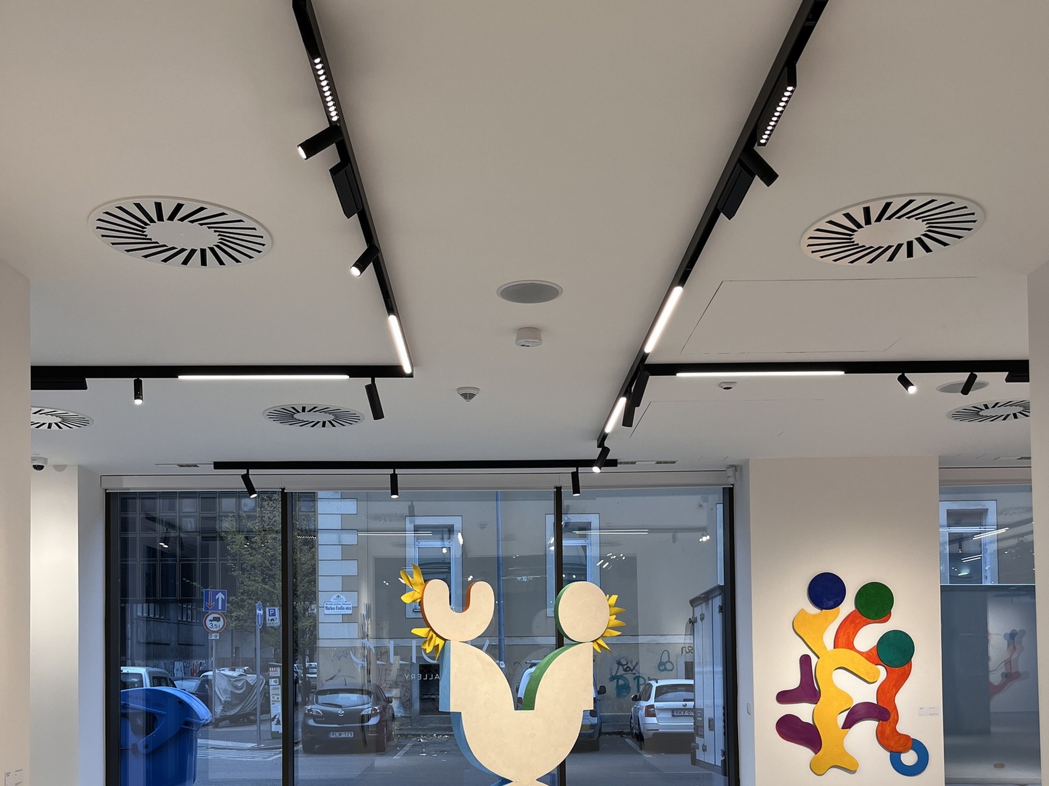
What Is Magnetic Track Lighting Installation? (And What Makes It Different from Fixed Downlights)
Magnetic track light installation is the process of mounting a low-voltage DC track rail, connecting a remote power supply, and attaching interchangeable lighting modules that lock into place through magnetic force combined with mechanical retention. Unlike fixed downlights — where every fixture position is permanent and every change requires ceiling damage — magnetic track systems let you reposition, swap, or upgrade modules without tools.
But that flexibility comes with installation complexity most guides ignore. You are not just drilling holes and twisting wires. You are installing an electrical infrastructure that must handle voltage drop over long runs, thermal expansion across seasons, and load distribution across multiple module types. Get the installation wrong, and the “flexible” system becomes a maintenance liability.
The Anatomy of a Magnetic Track System
A complete installation involves four integrated components. Understanding how they interact prevents the specification errors that only surface when the ceiling is closed.
Track Rail: The extruded aluminum profile that houses copper conductor strips. The rail is permanently wired to a remote AC-DC driver, so the ceiling surface never carries mains voltage. Profile dimensions determine compatibility — 20mm slim tracks suit residential and boutique retail, while 35mm commercial-grade tracks carry higher current loads for dense module configurations. View KWT LED track rail profiles and compatibility data →
Lighting Modules: These attach to the rail and draw power through magnetic contacts. Each module contains a DC-DC micro-driver that steps the track voltage down to LED operating levels. This matters during installation because modules from different voltage families (24V vs 48V) are not interchangeable — a mismatch destroys the micro-driver within minutes. See KWT LED module types and voltage families →
Power Supply / Driver: The AC-DC converter that steps mains voltage down to 48V or 24V DC. It sits remotely — in a ceiling void, electrical closet, or junction box. Driver selection dictates dimming protocol compatibility (0-10V, DALI-2, Bluetooth Mesh, or Zigbee). Driver placement and wiring are the most common failure points in field installations.
Accessories: L-connectors, T-connectors, X-connectors, end caps, and suspension kits. Not all manufacturers use compatible connector geometry. Verify ecosystem lock-in before you order — mixing brands on the same track run is the fastest way to create an electrical fault.
48V vs 24V: Why Voltage Dictates Your Installation Approach
The voltage you choose changes everything about how you install the system — wire gauge, maximum track length, bracket spacing, and even the type of conduit you use.
| Installation Parameter | 48V DC System | 24V DC System |
|---|---|---|
| Max track run per power feed | 15–20 meters | 8–10 meters |
| Recommended wire gauge (up to 15m) | 1.5 mm² | 2.5 mm² |
| Recommended wire gauge (15–20m) | 2.5 mm² | 4.0 mm² (or dual feed) |
| Max module count per run | 20–30 modules | 10–15 modules |
| Bracket spacing standard | 1.2–1.5 meters | 1.0–1.2 meters |
| Dimming protocol support | DALI-2, Bluetooth Mesh, Zigbee 3.0 | Basic 0-10V, limited DALI |
| Best project type | Commercial, hospitality, large retail | Residential, boutique, small retail |
48V systems allow longer runs and thinner cable because current draw is lower for the same power output. At 48V, a 200W load draws 4.2A. At 24V, the same load draws 8.3A — nearly double. That difference determines whether you can use standard 1.5 mm² cable or need heavy-gauge 4.0 mm² wiring.
Installation Methods Compared: Surface, Recessed, and Suspended
Before you touch a tool, you must choose the installation method. This decision is not aesthetic — it is structural, electrical, and contractual. The wrong method for your ceiling type creates coordination failures with other trades and cost overruns that appear only after the plaster is dry.
| Factor | Surface Mounted | Recessed | Suspended |
|---|---|---|---|
| Ceiling type | Concrete, existing plaster, suspended tile | Plasterboard (new build or full renovation) | High ceilings, atriums, exposed structures |
| Installation phase | Any time — retrofit friendly | During ceiling construction only | Any time — requires structural anchors |
| Track visibility | Visible profile (20–50mm height) | Flush with ceiling — trimless option | Visible track + suspension cables |
| Bracket / fixing method | Expansion bolts into concrete or timber | Backing plates + plaster stopping | Steel cables + structural anchors |
| MEP coordination | Low — surface routing avoids conflicts | High — must clear ducts, sprinklers, smoke detectors | Medium — cable paths must avoid HVAC airflow |
| Reconfiguration ease | High — accessible and visible | Low — requires ceiling access | High — accessible but needs ladder/lift |
| Cost per meter | Lowest | Highest (ceiling trade coordination) | Medium (structural verification required) |
| Best for | Retrofit, concrete ceilings, budget projects | New build, luxury retail, hotel lobbies | Restaurants, galleries, double-height spaces |
Surface mounting is the default for retrofit projects and concrete ceilings. It is fast, forgiving, and requires minimal coordination. The trade-off is visual — the track profile sits proud of the ceiling surface by 20–50mm depending on the series. In spaces below 2.8 meters ceiling height, surface-mounted tracks can feel visually heavy.
Surface-Mounted Installation
Surface mounting uses expansion bolts or self-tapping screws to fix mounting brackets directly to the ceiling substrate. For concrete ceilings, use M8 expansion bolts with a minimum embedment depth of 50mm. For timber joists or plasterboard with timber backing, use 35mm self-tapping timber screws.
Bracket spacing is critical. On a 35mm commercial track, brackets must not exceed 1.5 meters center-to-center. On 20mm slim tracks, reduce spacing to 1.2 meters. Long unsupported spans sag under module load — especially when pendant modules are installed. A 2-meter unsupported span with three pendant modules can deflect 3–5mm, which is visible to the eye.
Recessed Installation
Recessed installation integrates the track flush with the ceiling plane. This is the most aesthetically refined method — and the most coordination-intensive. The track must be installed during the ceiling construction phase, before plasterboard is finished.
The sequence is precise. First, install backing plates at stud positions. Then mount the track rail with leveling screws. Apply plasterboard around the track profile. Stop the plaster to the track edge. Sand to a 2mm shadow gap. If the track is not perfectly level before plaster application, the defect is permanent. A 2mm height variation over 3 meters is visible under grazing light.
Suspended Installation
Suspended installation hangs the track from the structural ceiling using steel cables or rods. This method suits high ceilings (above 3.5 meters), atriums, and spaces where the track is treated as a deliberate design element.
Cable spacing must follow manufacturer specifications — typically 1.2–1.5 meters for 35mm commercial track. In seismic zones or high-airflow environments, add sway restraints at mid-span. Verify structural load capacity with a structural engineer before installation. A 5-meter suspended track with 8 modules can exert 40–60 kg of static load plus dynamic loads from HVAC vibration.
Tools and Pre-Installation Planning
Most installation failures do not start on the ceiling. They start in the van — with the wrong tools, an unverified layout, or a power supply that does not match the track voltage. This section gives you the exact tool list and pre-installation verification protocol our field teams use before every project.
Essential Tools for Professional Installation
| Tool | Purpose | Specification |
|---|---|---|
| Laser level | Track alignment and horizontal reference | Self-leveling, ±2mm accuracy at 10m |
| Hammer drill | Concrete ceiling bracket fixing | Minimum 800W, SDS-plus chuck |
| Torque screwdriver | Consistent bracket screw tightness | 2–10 Nm range, prevents over-tightening |
| Digital multimeter | Voltage, continuity, and polarity verification | True-RMS, min 600V CAT III rating |
| Wire stripper / crimper | Cable preparation and terminal connection | 0.5–6 mm² capacity, ratchet type |
| Heat shrink kit | Insulation of DC connections | Assorted diameters, adhesive-lined |
| Thermal imaging camera | Post-installation heat spot detection | Minimum 80×60 resolution, <0.1°C sensitivity |
| Lux meter | Illuminance verification at designated points | Cosine-corrected, ±3% accuracy |
For commercial projects, a thermal camera is mandatory. It detects loose connections, overloaded conductors, and driver hotspots before they become failures. A $400 thermal camera prevents $4,000 in callback costs.
Pre-Installation Checklist: Layout, Load, and Voltage Verification
Run through this checklist before you unpack a single bracket. Every unchecked item is a potential change order.
- Confirm track voltage (48V or 24V) matches driver output and module ratings
- Calculate total module wattage and add 20% margin for driver sizing
- Verify ceiling substrate — concrete, plasterboard, timber, or suspended tile
- Map MEP conflicts — ducts, sprinklers, smoke detectors, cable trays
- Mark driver location with maintenance access (ceiling void or electrical closet)
- Confirm dimming protocol — DALI-2 bus wiring, 0-10V pairs, or wireless mesh
- Verify emergency lighting requirements and module compatibility
- Check connector inventory — straight, L, T, X, and end caps match the layout
- Measure and mark bracket positions at 1.2–1.5m centers (depending on track size)
- Pre-test all modules on a bench power supply before ceiling installation
Step-by-Step Magnetic Track Light Installation
This is the core procedure. Follow these four steps in sequence. Skipping a step or changing the order creates the failures that appear only after handover.
Step 1 — Mount the Track Rail with Precision
Set your laser level to project a horizontal reference line at the exact track height. For surface-mounted installations, mark bracket positions at 1.2-meter centers for 20mm slim track or 1.5-meter centers for 35mm commercial track. Drill pilot holes, insert wall plugs or expansion anchors, and fix brackets with a torque screwdriver set to 8 Nm.
Connect track segments using the correct joints. Straight connectors join linear runs. L-connectors handle 90° corners. T-connectors create branch lines. X-connectors allow four-way intersections. Clean all contact surfaces with isopropyl alcohol before assembly — oxidation on copper conductors increases contact resistance and causes voltage drop.
Leave a 3–5mm thermal expansion gap at every joint. Aluminum expands approximately 0.024mm per meter per °C. A 10-meter track in a climate with 30°C seasonal variation expands 7.2mm. Without expansion gaps, the track buckles, joints separate, and modules lose electrical contact.
Step 2 — Connect the Power Supply and Verify Polarity
Install the AC-DC driver in an accessible location — ceiling void, electrical closet, or dedicated junction box. The driver must never be buried behind permanently sealed ceilings. Run cable from the driver DC output to the track power input terminal.
Choose wire gauge based on total current and run length. Use this reference:
| System Voltage | Total Current | Run Length | Min Wire Gauge | Voltage Drop (Est.) |
|---|---|---|---|---|
| 48V DC | ≤ 4A | ≤ 10m | 1.5 mm² | < 3% |
| 48V DC | ≤ 6A | 10–15m | 2.5 mm² | < 3% |
| 48V DC | ≤ 8A | 15–20m | 4.0 mm² | < 3% |
| 24V DC | ≤ 6A | ≤ 6m | 2.5 mm² | < 3% |
| 24V DC | ≤ 10A | 6–10m | 4.0 mm² | < 3% |
Voltage drop must not exceed 3% for reliable module operation. At 48V, a 3% drop is 1.44V. At 24V, it is 0.72V. Excessive drop causes dimming inconsistency, color shift, and premature driver failure.
Verify polarity before energizing. Reversed polarity on multi-feed systems creates short circuits. Use a multimeter to confirm positive and negative conductors at both the driver and track terminals. Ground all metal track housings — even low-voltage systems require equipotential bonding for safety compliance.
Step 3 — Install Connectors and Test Continuity
Install L, T, and X connectors according to the layout plan. Tighten connector screws to manufacturer torque specifications — typically 1.5–2.0 Nm. Over-tightening deforms plastic housings. Under-tightening creates arcing and heat buildup.
Test electrical continuity across the entire track run before installing modules. Set your multimeter to resistance mode. Measure between the positive and negative rails at the far end of the track. A reading below 0.5 ohms indicates good continuity. An open circuit or high resistance indicates a loose connector, damaged conductor, or debris in the track channel.
Insulate all terminal connections with adhesive-lined heat shrink tubing. Standard electrical tape degrades in ceiling voids due to temperature cycling. Heat shrink provides a permanent seal against moisture and dust.
Step 4 — Attach Modules and Perform Load Testing
Attach modules to the track by aligning the magnetic contacts and sliding into position. Most commercial modules lock with an audible click. Verify mechanical retention by gently pulling each module — it should not detach without pressing the release mechanism.
Perform a full load test before handover:
- Energize at 100% load: Power on all modules simultaneously. Verify uniform brightness across the run.
- Run for 60 minutes: Allow the system to reach thermal equilibrium.
- Measure voltage at the far end: Compare against the driver output. Drop must not exceed 3%.
- Thermal imaging scan: Check connectors, driver housing, and module bodies for hotspots above 65°C.
- Dimming test: Verify smooth dimming from 100% to 1% without flicker or color shift.
- Emergency test (if applicable): Verify emergency modules switch to battery power within 0.5 seconds.
5 Installation Mistakes That Cost Projects Thousands
These are not theoretical warnings. Each mistake below comes from a real project our field team has remediated — with actual cost figures and prevention protocols.
Mistake 1 — Running Mains Voltage Directly to the Track
In 2024, a contractor in Lisbon ran 230V AC directly to a 48V magnetic track rail, treating it like a traditional mains-voltage track. Every module failed within minutes. The AC-DC driver must be installed upstream, and the track must never carry mains voltage.
Cost impact: $3,800 in module replacement plus 3 days of schedule delay.
Prevention: Mark all track rails clearly as “48V DC” or “24V DC” during delivery. Require the electrical contractor to submit a single-line diagram showing driver placement before rough-in inspection.
Mistake 2 — Incorrect Bracket Spacing on Long Track Runs
A restaurant in Dubai installed a 6-meter surface-mounted track with brackets at 2.8-meter centers — nearly double the recommended spacing. Under module load, the track developed visible sag that distorted lighting angles and created an unprofessional appearance.
Cost impact: $1,200 in reinstallation labor plus replacement ceiling paint.
Prevention: Follow manufacturer bracket spacing specifications precisely. For 35mm commercial track, never exceed 1.5 meters. For 20mm slim track, never exceed 1.2 meters. In seismic zones, reduce spacing by 20%.
Mistake 3 — Ignoring Thermal Expansion Gaps
“We didn’t think gaps mattered,” the Stockholm contractor told us. Three months after handover, thermal expansion had buckled a continuous 12-meter track at a corner joint. The electrical contacts separated, creating an intermittent fault that took three service visits to diagnose. The ceiling was intact. The track was not.
Cost impact: €2,400 in diagnostic labor, module replacement, and ceiling repair.
Prevention: Leave 3–5mm expansion gaps at every joint. For runs exceeding 10 meters, add an expansion joint connector. Account for seasonal temperature variation in your climate zone.
Mistake 4 — Mixing 24V and 48V Components
A hotel project in Warsaw mixed 24V grille modules onto a 48V track because the product codes were similar. The modules operated for 40 minutes, then failed sequentially due to overvoltage.
Cost impact: $4,200 in replacement modules plus emergency air freight.
Prevention: Create a voltage verification checklist. Label all components by voltage during unpacking. Test one module on a bench supply before ceiling installation.
Mistake 5 — Skipping the Load Test and Commissioning Phase
An office project in Berlin handed over a 60-module installation without load testing. Within two weeks, occupants reported flickering and dimming inconsistency. The root cause: a loose connector creating a 2-ohm resistance that caused voltage sag under full load.
Cost impact: €3,600 in after-hours diagnostic labor, ceiling access, and connector replacement.
Prevention: Mandate a 60-minute full-load test with thermal imaging and voltage measurement before handover. Document all readings in the commissioning report.
Post-Installation Testing and Commissioning
Installation is not complete when the last module clicks into place. It is complete when the system has been tested, documented, and signed off. This section covers the three tests that separate professional installations from callbacks.
Voltage Drop Testing Across the Full Track Run
Measure DC voltage at three points: the driver output terminals, the midpoint of the track run, and the far end. Record all readings. The voltage drop from driver to far end must not exceed 3%.
Maximum allowable: 3.0%
If drop exceeds 3%: upgrade wire gauge or add a mid-run power feed.
Thermal Performance and Flicker Verification
After 60 minutes of full-load operation, scan the entire installation with a thermal imaging camera. Acceptable temperature limits:
- Track rail surface: ≤ 45°C
- Module body (aluminum housing): ≤ 65°C
- Connector bodies: ≤ 55°C
- Driver housing: ≤ 70°C
For flicker verification, use a flicker meter or smartphone app with photodiode attachment. Percent flicker must be below 5% at 100Hz. Stroboscopic effect (SVM) must be below 0.5 per IEEE 1789-2015. Flicker above these thresholds causes occupant discomfort and violates WELL Building Standards.
Dimming Protocol Integration and Scene Programming
Test dimming performance across the full range — 100% to 1%. Verify smooth curves without dead zones or color temperature shift. For DALI-2 systems, program at least four default scenes: full power, evening, cleaning, and emergency. Document scene settings and provide a backup file to the facilities team.
Installation Decision Guide: Which Method for Your Project?
Use this decision table to guide stakeholder conversations and justify your installation method selection.
| If Your Project Needs… | Choose | Why |
|---|---|---|
| Fast retrofit on concrete ceiling with minimal disruption | Surface mounted | No ceiling demolition, install during off-hours, lowest labor cost |
| Flush ceiling with invisible hardware for luxury retail or hotel lobby | Recessed (trimless) | Cleanest aesthetic, track reads as architectural detail, not equipment |
| Lighting over dining tables or reception desks in high-ceiling space | Suspended | Creates visual layering, positions light at optimal height for atmosphere |
| Seasonal layout changes in retail or pop-up environments | Surface mounted or recessed | Both allow tool-free module repositioning; surface is faster to install initially |
| Emergency lighting integration in hospitality or healthcare | Recessed or surface mounted | Easier to coordinate emergency modules with central battery systems |
| Budget-first decision with acceptable visual compromise | Surface mounted | Lowest material and labor cost, no ceiling trade coordination required |
Related Resources
- Magnetic Track Lighting Systems: A Complete Specification Guide — System anatomy, module selection, and TCO analysis for commercial projects.
- 48V vs 24V Magnetic Track Systems: Voltage and Control Guide — Deep dive into voltage selection, dimming protocols, and smart building integration.
- Emergency Lighting Integration for Magnetic Track Systems — How to specify and install emergency modules compatible with low-voltage track infrastructure.
FAQs About Magnetic Track Light Installation
Need professional support for your magnetic track lighting installation?
Get our free Magnetic Track Installation Checklist or talk to our engineering team about OEM custom lighting solutions, project-specific wiring diagrams, and on-site commissioning support for commercial rollouts.
15 Years | 2,500㎡ Factory | 50+ Countries | OEM No MOQ